|
|
|
|
News The Project Technology RoboSpatium Contribute Subject index Download Responses Games Gadgets Contact <<< Lander 2 R4-Automuseum >>> R3 - constructionRead how to control a roverDrive Curiosity Pi The video about the construction detailsUpdates: Parts list
Components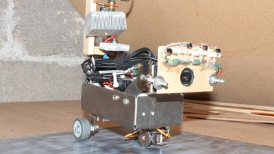
The Raspberry Pi, a cheap tiny computer, operates as the host computer of R3. The dimensions are approximately 20 x 12 x 22cm (LxWxH) including power pole. The housing could be slightly larger. When I build this Rover I did not consider that a powered USB hub has also to be to stored inside of the housing. The webcam is a Logitech C525 with a maximum resolution of 1280x720 Pixel. The autofocus is able to catch even very close by objects. The camera can be turned around it's horizontal axis by a servo, so you can observe objects below and above the Rover. 5 LEDs are used as headlight. 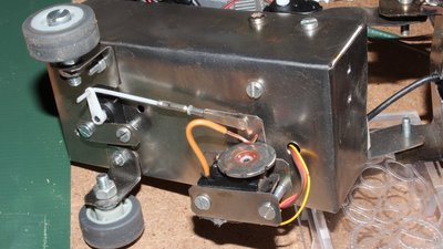
The Rover is a threewheeler. The two rear wheels are fixed and the single front wheel is driven by a hacked servo while the steering is done by another servo. There is a special reason for using a metal front wheel and the sliding contact besides of it: If the Rover is driving on a metal plate, the Raspberry Pi can communicate with other computers by a single GPIO pin. Inside of my RoboSpatium you can control the Space Shuttle, which is connected to an Atmega8 microcontroller. Electronics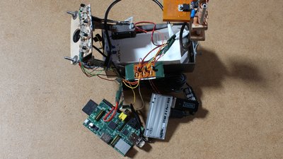
The electronic is much simpler than at my previous Rovers. The GPIOs make it easy to control peripherals. 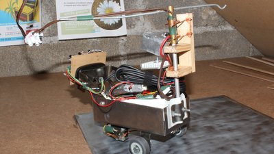
The cabling from the power supply to the Rover is long and thin. To be able to copmpensate the voltage drop at those cabling, it is attached to an power output of 12V. At the power pole of the Rover those 12V are converted to just 5V. The WLAN stick is very sensible against voltage peaks and the voltage regulators I have used have a maximum current of just 2A. Hence I am using two of them. Number one (great heat sink) is for the Raspberry Pi and the USB hub and number two for the servos and the LEDs. 
Control softwareAt the column download you can find a simple version of the used software.More questions about R3?There is a topic about the rover at the Raspberry forum.You can find my mail address at the column imprint <<< Lander 2 R4-Automuseum >>> News The Project Technology RoboSpatium Contribute Subject index Archives Download Responses Games Links Gadgets Contact Imprint |
|
|