|
|
|
|
News The Project Technology RoboSpatium Contribute Subject index Download Responses Games Gadgets Contact Lander 2 with Raspberry HQ cameras - ConstructionThe video about Lander 2Raspberry HQ camera module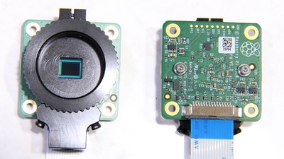
The HQ camera module from the Raspberry Foundation, which is designed for high-quality photo shots, has a physical resolution of 4056x3040 corresponding to 12 megapixels. The module is delivered without a lens, an appropriate lens must be screwed to the CS bracket. Two variants are offered: 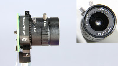
The smaller lens has a focal length of 6mm, ... 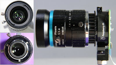
.. the larger of 16mm. With the 16mm lens, the adapter ring must be installed, otherwise the distance to the image sensor is not correct and you will only get blurred pictures. The aperture can be reduced by the rear ring from 1.4 (=open), up to 16 (=smallest opening). The focus is adjusted via the front ring and a minimum distance of 20cm to the target object is needed to get non blurred results. If you want to get closer than these 20cm, you can unscrew a ring on the camera adapter to move the lens away from the image sensor. Mechanics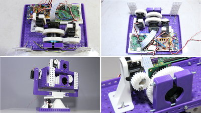
The mechanics were created with my 3D printer. The two cameras are arranged one above the other. Parts list:
Electronics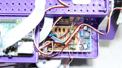
The transistors required to amplify the electrical power of the GPIOs are located on an extra board. A step-down converter reduces the 12V input voltage to 5V for the servos and the Raspberry Pis. A total of 42 LEDs can be switched in four brightness levels. 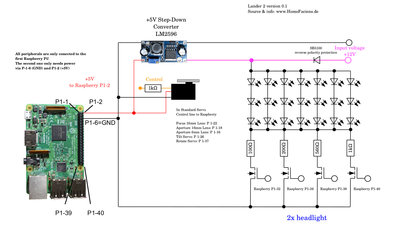
Circuit diagram DownloadThe 3D files of the mechanics as well as the circuit diagram are included in the download package (14MB)Try the cameraYou can control my cameras through a browser in my RoboSpatiums.News The Project Technology RoboSpatium Contribute Subject index Archives Download Responses Games Links Gadgets Contact Imprint |
|
|