|
|
|
|
News The Project Technology RoboSpatium Contribute Subject index Download Responses Games Gadgets Contact <<< R14 pi-top[4] R18 ESP32-CAM >>> R15, Rover based on a Hoverboard - ConstructionThe video about R15Mechanics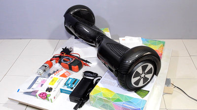
R15 was created from a so-called hover or balance board. I was curious to find out what electronic components you get in return for your money by purchasing one of those cheap hoverboards. Especially the high-torque engines sparked my interest. In addition to the board, I needed other parts to put the rover into operation and control it via a browser interface: Parts list:
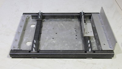
The chassis consists of iron square tubes with a base plate made of sheet metal. 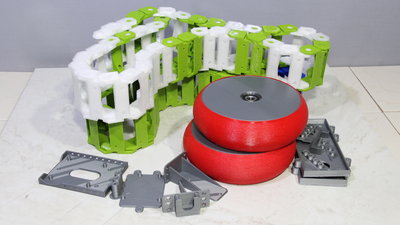
I turned on my 3D printer for the tracked drive. The track links are made of PETG and the rear wheels have tires made of material called Flex-Hard on rims made of PLA. All other parts, such as the camera mount, are also made from PLA. 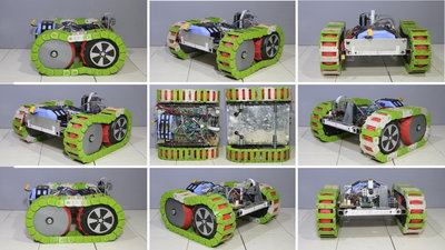
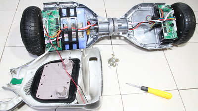
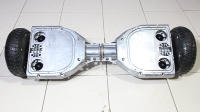
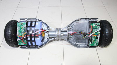
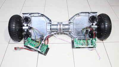
When fully assembled, the whole thing still looks very much like a prototype: Disassembly of the Hoverboard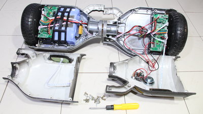
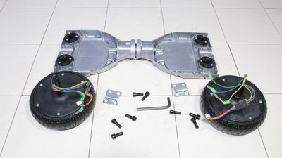
The first step was to disassemble the vehicle, all you need for this is a Phillips screwdriver and a 6mm hexagon tool. 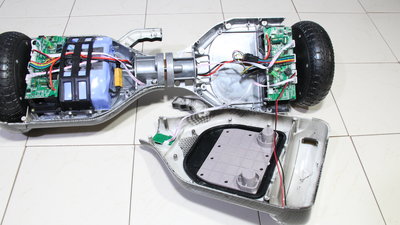
Electronics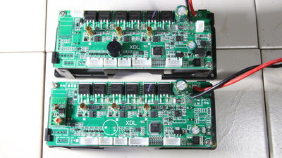
I decided to take over the motor control with an Arduino Uno at the MOSFET driver ICs, for which the pin layout of the unlabled chips had to be explored as shown in the video. 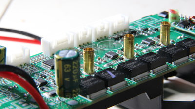
To prevent the signals from the microcontroller on the board from overlapping those of the Arduino Uno, the two control lines must be disconnected from the board. With a soldering iron and the pointed blade of a cutter knife, I carefully bent the pins upwards. 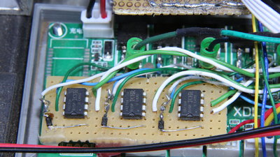
As life plays, the pins of one IC on the second board broke during the desoldering procedure. A quick online research brought to light that the ICs are most likely of the type IR2104. If you order the version for through-hole assembly and remove the three SMD ICs on the board, everything can be soldered much more conveniently. The diode and the capacitor could also be replaced by larger components for through-hole mounting, but I have soldered the original SMD components. 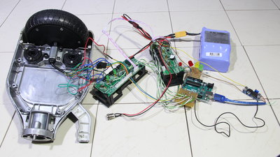
In a first attempt, I did not read the Hall sensors - accordingly the motor runs very rough. Even if the input voltage of the Hall sensors is 5V, the logic levels at the outputs are 3.3V - this signal level is recognized by the Arduino Uno as being a HIGH signal. SoftwareThe software, especially the motor control, is in a very early stage of development. A basic idea behind R15 is to explain the motor control of brushless drives in more detail in my chapters on physical computing. This will be done step by step in the next weeks/months/years. Be patient, I think it will be worth it!DownloadThe 3D files of the printed parts as well as the very early version of the control software are available as download package.Test drivesHave a look at my RoboSpatium to see what robots are currently available for a test drive. Have fun!<<< R14 pi-top[4] R18 ESP32-CAM >>> News The Project Technology RoboSpatium Contribute Subject index Archives Download Responses Games Links Gadgets Contact Imprint |
|
|