|
|
|
|
News The Project Technology RoboSpatium Contribute Subject index Download Responses Games Gadgets Contact WinchBot 2.0The video about WinchBot 2.0RS Components video "for the inspired"Building the pyramid in fast forward
WinchBot 2.0 is the version of my cable bot that was displayed an the stand of RS Components on the SPS/IPC Drives in Nuremberg 2017. Parts listMy WinchBot originates from a cooperation with RS-Components which is why links in the table point to their online shop.
Mechanics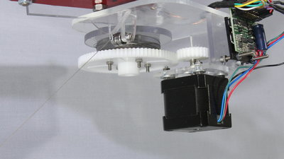
The mechanics is identical to that of WinchBot 1.5, I only did som experimentation with the transmission of the winches: I am now using gears having 24 teeth on the motor shafts to speed up the WinchBot. An attempt with even larger gears having 36 teeth failed - caused by the lower torque on the winches, the robot started skipping steps. The maximum phase current of the stepper motors I am using is 1.68A, while the Gekko drivers can deliver up to 3.5A, so you can try to use more powerful motors If you'd like to speed up this bot. Electronics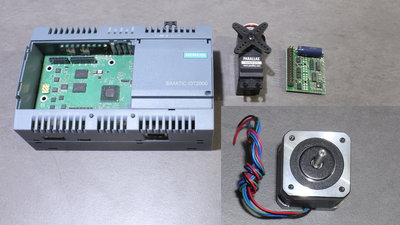
5 stepper motors with driver chips, 3 servos and a SIMATIC IOT2020 are needed to drive WinchBot 1.5. The stepper motors at the winches draw a current of 1.68A at 2.8V and they are driven by Geckodrive G250X in 10 microsteps per full step. The stepper motors at the gripper platform draw a current of 400mA at 12V, so they are weaker but not as heavy as the winch motors. They are drivem through L293D chips in full steps. The servos are used to rotate and open or close the gripper. 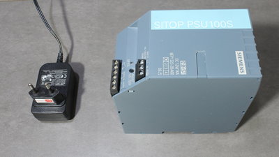
I am using a SITOP PSU 100S with an output voltage of 12V at up to 14A to feed the SIMATIC and the stepper motors with electricity. The servos are connected to a second power supply with an output voltage of 5V at up to 3A. 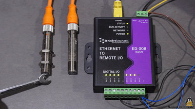
During the exhibition I used two inductive sensors to recalibrate the WinchBot from time to time while it was running. All GPIOs of the IOT2020 were in use, which is why I connected the sensors to a Brainbox to observe their current state. The Brainbox type ED008 has 8 digital input/output pins that can be controlled by sending ASCII codes over the network. With that, only short cables are needed to connect the sensors with the Brainbox while you can observe the state of the GPIOs through any distance using a computer network. 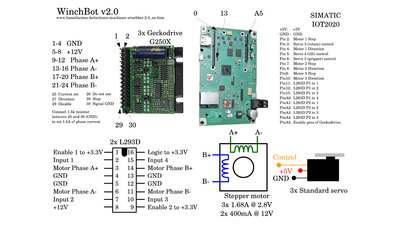
Software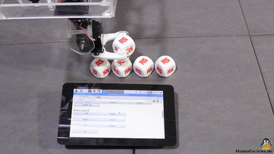
Same as with its precedessors, I am using a web interface to control WinchBot 2.0. The webserver "Monkey" is running on the IOT2020, so that you can control the WinchBot using any computer running a browser. You can get the software including scematics at the column download. News The Project Technology RoboSpatium Contribute Subject index Archives Download Responses Games Links Gadgets Contact Imprint |
|
|