|
|
|
|
News The Project Technology RoboSpatium Contribute Subject index Download Responses Games Gadgets Contact <<< Extruder V6.0 Extruder V7.0 >>> Direct granules extruder V6.1 and 6,2The video about Direct Granules Extruder V6.1 and 6.2.Extruder V6.1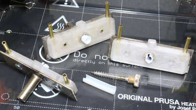
The version 6.0 of my direct granule extruder shown in the previous chapter is based on a threaded connector with a Teflon insert, which has resulted in very good print quality. Version 6.1 adopts this principle; the only change concerns the water cooling. In the previous versions, I had soldered a steel plate to the extruder tube and glued a 3D-printed component to it, through which the water circulates. New water cooling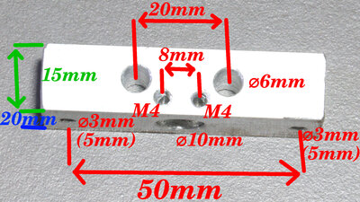
In the new version, I'm using an aluminium block measuring 20x15x60mm, with holes for the water cooling system and the extruder tube mounting. A 3D-printed part serves as a template for these holes. To mount the extruder tube, M4 threads are cut into the corresponding 3mm holes. The mounting holes on the printer have a diameter of 3mm for version 6.1 with the Teflon insert and centered extruder screw. For version 6.2, an offset of the screw is required. For this purpose, 5mm holes are drilled so that the water cooling system can be mounted in a shifted position. 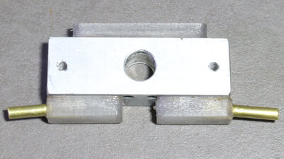
The 6mm holes for the water circuit are sealed with printed PETG parts using superglue. Over-extrusion should be used when printing these parts to ensure they are watertight. 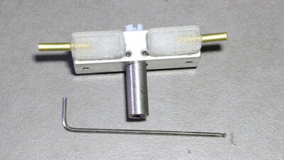
The advantage of the new water cooling system is that the extruder tube is now only clamped in place with screws, allowing for quick and easy replacement. Furthermore, the extruder tube can be moved within this mount, which allows for adjustment of the transition zone between the cold and hot sides - a crucial parameter. The extruder with the Teflon insert performs as well as ever. Anyone wanting to delve into the new technology of 3D printing with a direct granule extruder should first replicate version 6.1 shown here, as this design has proven to be very forgiving in my experiments. Printing with PLA allows you to take your first steps with granule printing and gain experience - it should be worthwhile! Another rocky road to V6.2
A full-metal extruder was the next goal, which meant countless hours, days, weeks, even months of experimentation before I finally found a reliably functioning design. As mentioned in a previous video, the inner wall is too rough after drilling out the threaded connector, causing the powder to jam the extruder. Smoothing the inner wall was therefore necessary, and I did this in several different ways: Approach 1 involved polishing the inside with abrasives of varying grits, approach 2 involved coating it with enamel, and finally, approach 3 involved fabricating inserts from smooth sheet steel. All three approaches led to more or less the same result: Initially, the extrusion rate was nice and high, and the printing worked perfectly. But after only a few printed layers, the extrusion rate plummeted. The reason for this is that heat conduction along the extruder tube causes the plastic to heat up through the inner wall. This creates a lubricating film of liquid plastic in the transition zone. This, in turn, causes the plastic in this zone to rotate with the screw, thus reducing the extrusion rate. So I tried adding "brake pads" in the form of metal strips, either by gluing, soldering, or enameling them in place, but this didn't have the desired effect - the extrusion rate still dropped dramatically after a while. Version 6.2
The resulting idea greatly simplifies the extruder design: The tube now consists of a tube with smooth walls, as in the initial experiments. The sticking to the screw and subsequent rotation of the plastic in the softening zone is prevented by a simple trick: The wood screw, acting as the auger, is not positioned centrally, but rather so that it almost scrapes against the wall at one point. On the opposite side, the gap to the extruder wall is correspondingly larger. This gap is necessary to allow the air trapped in the powder to escape and for pressure equalization to occur - the simple wood screw has a constant pitch and core diameter. When the film of liquid plastic forms on the tube wall and the material sticking to the screw rotates with it, the still-solid inner part is churned and transported further downwards. 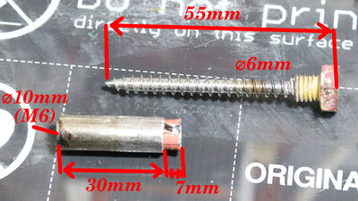
Here too, I had to conduct several experiments until I found a tube/screw combination and extruder length that worked well. I'm using a threaded connector that's only 30mm long with a 6mm screw. The bore 8.5mm is again covered with spot-welded sheet metal. This sheet protrudes about 7mm at the top, has a slot about 2mm wide, and is slightly cone shaped to facilitate the entry of the plastic powder. 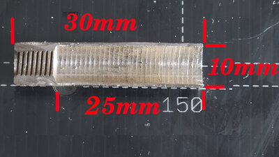
The 8.5mm bore of the thread connector. 5mm of the thread remain for the nozzle. 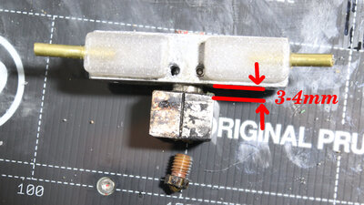
The transition zone from the cold end to the hot end is adjusted to only about 3mm. The heating block is a 20x20x10mm aluminum block with holes for the extruder tube, the heating cartridge, and the temperature sensor. 
The screw is set in rotation by the previously used stepper motor with a 3:1 reduction ratio. The screw is no longer "floating" but is firmly clamped in the adapter. 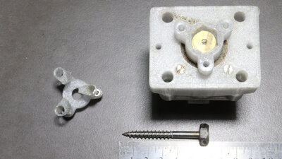
This is achieved by using washers that are placed in the adapter so that the screw is tight when the "lid" with the stirrer is screwed on. 
The correct screw insertion depth is important: It must almost touch the brass nozzle at the bottom of the extruder. Spacers can be added to the gearbox mounting until this distance is correct. DownloadThe 3D files and the sketch of the extruder are available in the download package.Print example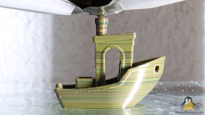
Benchy Dimensions: 60x31x48mm Layer hight: 0.2mm Extrusion width: 0.5mm Print speed: 15mm/s for small perimeters, 40mm/2 for all other struktures at an acceleration of 10000mm/s2 Print time: 1h The goal of this print wasn't speed or aesthetics, but rather using two significantly different speeds: Small perimeters are printed at only 15 mm/second, while all other structures are printed at 40 mm/s. The acceleration is set to 10,000 mm/s². Compared to filament extruders, screw extruders have some unique characteristics, which I will discuss in a later chapter. One of these is that the extrusion rate doesn't increase linearly with the screw's rotational speed. When transitioning from the window openings to the roof, the printer starts printing quickly again after a long, slow print. However, it takes time for the necessary pressure to build up in the extruder tube. As a result, underextrusion occurs, which is visible as gaps on the outer wall. Pressure advance was disabled for this print, but it would certainly need to be implemented differently than on filament printers. The chimney shows that the extrusion rate is proportionally higher at slow printing than at fast printing - this structure was obviously printed with over-extrusion. <<< Extruder V6.0 Extruder V7.0 >>> News The Project Technology RoboSpatium Contribute Subject index Archives Download Responses Games Links Gadgets Contact Imprint |
|
|