|
|
|
|
News The Project Technology RoboSpatium Contribute Subject index Download Responses Games Gadgets Contact <<< Direct granules extruder V2 Direct granules extruder V4 >>> Direct granules extruder version 3My application video for the Shuttleworth Foundation gives a first look on how the extruder V3 works.The Shuttleworth Foundation (shuttleworthfoundation.org) supports open source projects. Anyone with appropriate ideas can apply. The second video shows details of the constructionThe Third video tells a bit more about the evolution of the designThe fourth video is for the final round of the Hackaday Prize 2021The fifth video demonstrates how to print sugarSince Extruder V3 is a submission for the Hackaday Prize 2021, you will of course also find a page on Hackaday about the project with some additional information. Extruder Details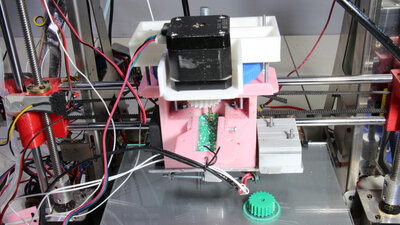
Version 3 of my granulate extruder works (finally) reliably. Earlier versions had problems with clogging of the nozzle, which occurred particularly often after switching the printer on again and heating up. The printer mechanism is a Zonestar QR2, from which I also took the heating element and the stepper motor for driving the auger (5mm wood screw). 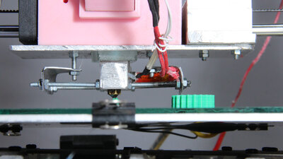
In order to meet the deadline for this year's application round, I created an interim report with the video. The same applies to the build instruction shown here: It is a rough description of the extruder, more detailed information will follow in the coming weeks/months/years... 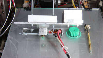
The series of pictures gives a good overview of the construction. Everything is handmade. 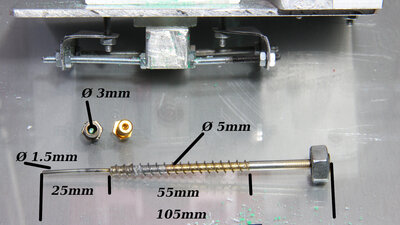
The central element is the auger screw: This consists of a simple wood screw with a diameter of 5mm and a total length of 105mm. At the top I hard soldered a 25mm long piece of 1.5mm wire. I widened the neck of the brass nozzle with a 3mm drill so that the plastic can pass this point with less resistance - the tip of the screw would otherwise lead to clogging issues. An M8 nut is soldered to the screw head. 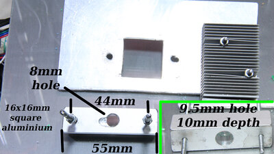
The "cold side" of the extruder: The central drilling is done first with an 8mm drill. Then the hole on the underside is widened to 9.5mm with a depth of 10mm. A small groove, about 3mm deep, is milled on the top, which improves the forwarding of the granulate. 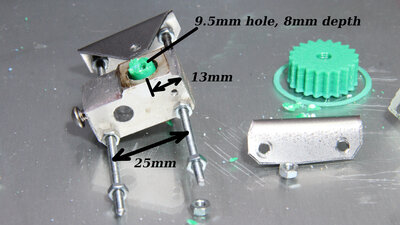
The "hot side" of the extruder is also made of 16x16mm aluminum: First, a 5mm hole is drilled about 13mm from the edge. Then this hole is widened at the top to 9.5mm, about 8mm deep. The thread for the brass nozzle is made with a 6mm thread cutter. Holes for the heating cartridge (diameter 6mm) and the temperature sensor (diameter 2mm) are drilled so that there is sufficient distance to the central hole. About 3mm of material is filed on the upper side, so that only a small contact area with the coldend is formed. Finally, two 3mm holes with a distance of 25mm are drilled on the lower edge. Two 90mm long threaded rods are screwed in there. Hotend and Coltend are screwed together using the two metal angles, made from 0.5mm sheet metal. The threaded rods allow you to adjust the components so that the central holes of the Coltend and Hotend are in line. I filed about 3mm from the upper edge so that there is only a small contact area with the glass block. This reduces the heat flow to the coldend. 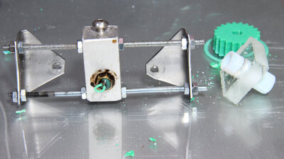
Thermal insulation: In order to keep the heat flow from the hotend to the coldend small, there is a piece of 8mm glass as an insulator between the two components. I cut the 25x25mm block with the help of an electric tile cutter with water cooling for the diamond disc. I made the 9.5mm hole with a Dremel and a diamond-coated drill, also with water cooling. A Teflon tube (about 10mm outer and 8mm innber diameter, 26mm long) runs from the coldend to the hotend and ensures the least possible friction on the walls. "Pellets"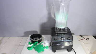
There is a lot to say about how to create granules (coming soon), here is just the short version: Failed prints from PLA are shredded with a blender... 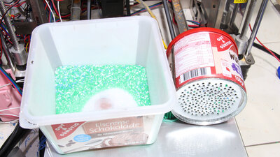
... then the shredded plastic is sieved. The grain size has a major influence on the functioning or non-functioning of the extruder! The can I used as a sieve has 2mm holes. Anything that doesn't pass the holes is put back into the mixer. DownloadThe 3D files, made with OpenSCAD (including *.stl files) are available as Download-Package. That part of the extruder is identical to Version 2.Sample prints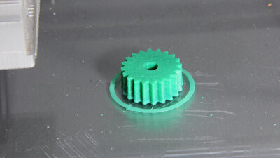
The print made in the first video is a gear. In good RepRap tradition, it is the pinion on the stepper motor of the extruder. A 1.0mm nozzle was used for printing in order to avoid clogging due to impurities in the granulate made from old parts. Although the granulate consists of green and white grains, the plastic has been mixed relatively homogeneously to a light green color. Material: PLA Dimensions: 25x25x10mm Nozzle: 1.0mm Layer height: 0.2mm Extrusion width: 0.7mm 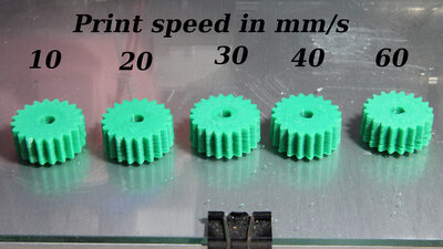
In the second video, I printed these gears at different speeds. The lack of an object cooling fan is particularly noticeable when printing at 60mm/s (far right) by the tips of the teeth bending upwards. There is also a flaw at the bottom of this gear, because I moved the printer on the table during the printing process in order to take different video shots. Material: PLA Dimensions: 25x25x10mm Nozzle: 1.0mm Layer height: 0.2mm Extrusion width: 0.7mm 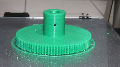
In the third video, I printed the main gear of the extruder as a spare part. It took 4 hours to finish the job. Material: PLA Dimensions: 90x90x37mm Print speed: 30mm/s Nozzle: 1.0mm Layer height: 0.2mm Extrusion width: 0.7mm 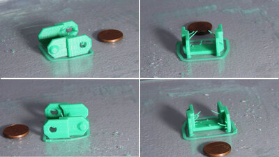
The chain link was also created in the third video. For the first time I used a 0.6mm nozzle. The object cooling fan is still missing. Stringing can be clearly seen, the closing of the nozzle obviously does not work yet. Material: PLA Dimensions: 27x25x12mm Print speed: 20mm/s Nozzle: 0.6mm Layer height: 0.2mm Extrusion width: 0.5mm 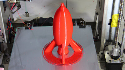
Example "Rocket": Material: PLA Dimensions: 100x100x150mm Print speed: 30mm/s Nozzle: 0.6mm Layer height: 0.2mm Extrusion width: 0.5mm The rocket was printed during the Hackaday Prize video (openSCAD and STL files available as Download). On the tip you can see, that I should have screwed on the part cooling fan. 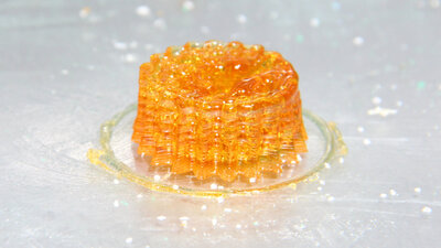
Example "Pinion": Material: Sugar (Sucrose) Dimensions: 25x25x10mm Print speed: 10mm/s Nozzle: 0.6mm Layer height: 0.2mm Extrusion width: 0.5mm A copy of the pinion on the stepper motor of the extruder has been printed here from sugar. Sugar is the generic term for a whole range of different, sweet-tasting substances - the household sugar used here consists of sucrose. The sugar comes out of the nozzle in a light brownish color. The reason is the caramelization reaction that takes place at temperatures above around 140°C - a pleasant smell spreads in my video studio that made me feel hungry. The surface of the gear is not as smooth as it is when printing with ordinary plastics. The reason is the surface tension in combination with the significantly lower viscosity of the molten sugar: The tip of the nozzle is always surrounded by a drop of liquid sugar. So it is surprising that the only 3mm small teeth of the gear are clearly visible. The gear is far from perfect, but at least recognizable as such for a first try. At the top, the tendency of the liquefied sugar to form droplets can be clearly seen. On the other hand, however, you can also see the layered structure of the print. 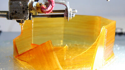
Example "Octagon": Material: Sugar (Sucrose) Dimensions: 100mm Diameter on the base Print speed: 10mm/s und 20mm/s Nozzle: 0.6mm Layer height: 0.2mm Extrusion width: 0.5mm In this experiment, I had initially printed the walls of the octagon at 10mm/s, which worked great. Later I increased the speed to 20mm/s, which soon afterwards led to a part of the wall breaking out. This happened when the printhead was on the opposite side. Obviously, due to the increased print speed and the cooling of the sugar, excessively high stresses built up in the walls and led to them breaking out. Household sugar is still damn brittle even in slightly caramelized form! 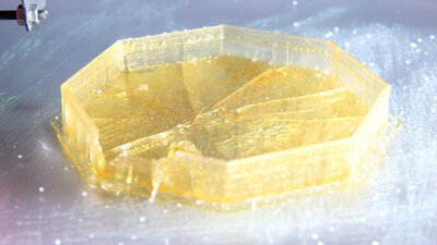
Example "Octagon": Material: Sugar (Sucrose) Dimensions: 100mm Diameter on the base Print speed: 30mm/s Nozzle: 0.6mm Layer height: 0.2mm Extrusion width: 0.5mm The brittleness can also be seen elsewhere: If the print bed heating is switched off after a successful print, the object destroys itself. 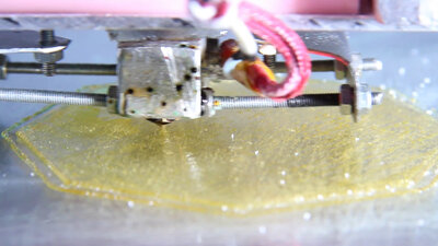
Example "Octagon": Material: Sugar (Sucrose) Dimensions: 100mm Durchmesser an der Basis Print speed: 30mm/s Nozzle: 0.6mm Layer height: 0.2mm Extrusion width: 0.5mm If the printing is sufficiently fast, the sugar does not have time to form drops before it solidifies. With that, nicely smooth surfaces can be printed. 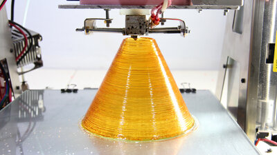
Example "Cone": Material: Sugar (Sucrose) Dimensions: 100mm Diameter on the base Print speed: 10mm/s Nozzle: 0.6mm Layer height: 0.2mm Extrusion width: 0.5mm As with all materials in 3D printing, you must keep the properties of sugar in mind in order to be able to achieve good results. 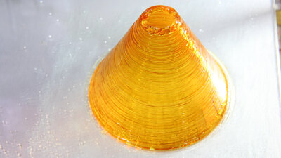
Example "Cone": Material: Sugar (Sucrose) Dimensions: 100mm Diameter on the base Print speed: 10mm/s Nozzle: 0.6mm Layer height: 0.2mm Extrusion width: 0.5mm With increasing height, the diameter of the cone becomes smaller. This means that the sugar in one layer has not cooled down completely before the next layer is printed. As a result, drops form on the upper edge of the wall, which ultimately led to the printing being canceled. Better results should be achieved with a heated chamber and a part cooling fan. 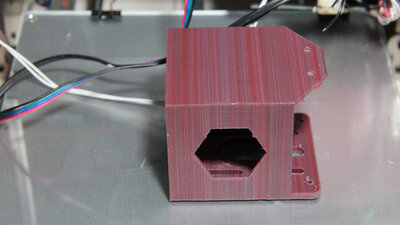
Example "Stepper motor mount": Material: PLA Dimensions: 70x77x66mm Print speed: 30mm/s Nozzle: 1.0mm Layer height: 0.2mm Extrusion width: 0.45mm Sample print with colored base material (red, blue, green and white granulate). Due to the relatively small volume of the extruder, there is no complete mixing of the grains on the way to the nozzle. As a result, the individual layers differ significantly in color. <<< Direct granules extruder V2 Direct granules extruder V4 >>> News The Project Technology RoboSpatium Contribute Subject index Archives Download Responses Games Links Gadgets Contact Imprint |
|
|