|
|
|
|
News The Project Technology RoboSpatium Contribute Subject index Download Responses Games Gadgets Contact CNC V3.x seriesSelf replicating CNC for 194 (or more) countriesThis series of CNC machines is a submission to the HackadayPrize2016.You can find my project on Hackaday: Self replicating CNC for 194 (or more) countries.
I made it to the Finals of HackadayPrize2016! The promotion video recorded for this year's HackadayPrize.I have created multiple CNC machines (plotter, CNC v0.5, CNC v0.6, CNC v2.0, CNC v2.1) using low tech tools and commonly available materials that have been replicated in many countries on this planet around the world. Often I have been asked what motors or electronics can be used instead of the ones I used in a demonstration, especially in places with no access to 24hr delivery services. Furthermore people want a fully functional 3 axis machine rather than the servo driven third axis I was using in some designs. There were also several requests for making my CNC machines work with software like GRBL (Step/Direction). With the CNC V3.x series I'd like to atempt to solve all of those issues (and more if you have a request) in my new CNC design. My main build design goals are: 1. Using commonly available materials throughout 2. Suitable for a diverse range of drive technologies 3. Build with low tech tools (so that anyone anywhere can replicate it, thus "self replicating") 4. Ultimately build a machine that can build a duplicate machine itself (self replicating) If you think this project is worth spending some money to compensate for the time and money I am spending to turn things into something of value to you and the global community, I am asking for your support by making a small donation to help with my costs on this project. Please click the "Donate" button on any one my pages to help further and support the global community with me, as I am working hard to enable and educate anyone looking to benefit themselves. 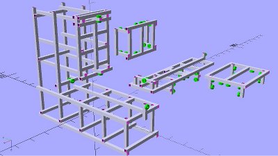
For the first time I have designed a CNC using CAD software. The program of my choice is OpenSCAD, since I prefer typing source code over clicking on a colored desktop with a mouse. The framework is based on steel square tubes of the dimensions 20x20mm with 2mm thickness. Here you can get the OpenSCAD file. The video about my linear driveIn this video I am having a close look at the accuracy of my DIY linear drive using a dial indicator. Linear drive using a linear sensor from an old printerUsing the printhead sensor from an old inkjet for a DIY linear drive is demonstrated in this video. Linear drive with an optical computer mouseIn this video I am using an optical mouse as linear sensor. Mesurement results Logitech G303 with up to 12000DPI 1.) 12000DPI Physical resolution with 12000DPI hardware adjustment: 12598DPI Error when going to a point from right: 20μm at a drive distance of 2x 300μm, 30μm at a drive distance of 2x 600μm. Driving to one point from right with low speed on return path: -130μm deflection to the left. Driving to one point from right with changing speed on return path: 20μm deflection to the right after the first run, 140μ deflection to the right after 15 runs. 2.) 3000DPI Physical resolution with 3000DPI hardware adjustment: 3150DPI Driving to one point from right with low speed on return path: -130μm deflection to the left. Driving to one point from right with changing speed on return path: 10μm deflection to the right after the first run, 100μ deflection to the right after 15 runs. 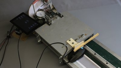
I had another run with the mouse mounted in X direction of the optical sensor pointing to carriage movement. 1.) 12000DPI Physical resolution with 12000DPI hardware adjustment: 12268DPI Error when going to a point from right: 10μm (deflection to the right) at a drive distance of 2x 300μm, -10μm (deflection to the left) at a drive distance of 2x 600μm. Driving to one point from right with low speed on return path: -220μm deflection to the left. Driving to one point from right with changing speed on return path: 20μm deflection to the right after the first run, 180μ deflection to the right after 15 runs. Source code of the Raspberry Pi software used to control the drive Optical sensors with quadrature output I got lots of feedback about the video using optical mice as linear sensors. An interesting approach is to read the data directly on the pins of certain chips that encode motion as quadrature encoders: Hdns2000 Hdns2100 Hdns2200 Om01 Om02 ADNS2051 ADNS2030 Uic1001 (Thanks to Michele for the device list) There is more science to be done... Quality check of my roter motorsResults
News The Project Technology RoboSpatium Contribute Subject index Archives Download Responses Games Links Gadgets Contact Imprint |
|||||||||||||||
|
|