|
|
|
|
News The Project Technology RoboSpatium Contribute Subject index Download Responses Games Gadgets Contact <<< CNC v2.0 CNC v3.x series >>> CNC V2.1The video about CNC v2.1Videos of replicasRudi from Germany has recorded a detailed video. He is using LinuxCNC:https://youtu.be/DFNpF2QBaxY Peter from Austria: https://youtu.be/0ErJPFKXAgk Nicolas from France: https://youtu.be/r73QuL5oLHI Michael has made a copy of CNC v2.1 and you can find his instruction with additional tips and tricks on his maker page (German, but Google translate helps). Leave a comment or send me a mail if you have made videos of your replicas, too - thanks! Version 2.1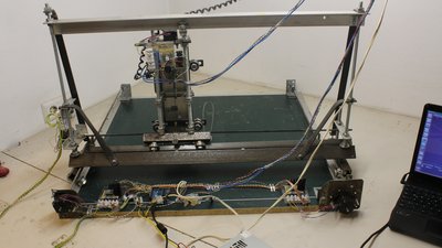
There were many requests about using my CNC version 2.0 with bipolar stepper motors, which is why I have done that conversion. Parts list for upgradeYou can find the parts list for the mechanics in the chapter about CNC v2.0.
Changes made on the mechanics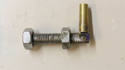
I have added a lubrication system which isn't my invention: You can see similar systems at old steam engines. A piece of brass tube is used as oil reservoir and a 1mm drill hole forwards the oil to the threaded rod. Use oil with a high viscosity and fill in just a few drops or else it will start dripping. Christian left a comment that there is some cotton wool inside the brass tubes of old steam engines to avoid dripping. Thanks for that hint! 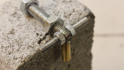
I have drilled out the 6mm threads inside 10mm bolts. After that I have inserted a piece of a 6mm threaded bar and used 2 nuts to tighten that thread slightly so that you can still turn the rod easily by hand. The nuts are fixed on the bolt using hotglue. Epoxy is stronger, but you can make corrections more easily with hotglue if the thread is jamming or if there is still too much backlash. 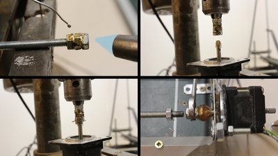
The linkage between 5mm motor shaft and 6mm threaded rod is composed of three 6mm nuts that are soldered. With a 1.5mm drill hole and the slotted motor shaft, a piece of 1mm wire can be used to connect the adapter with the motor reliably. You can align the adapter upright with a drill press when gluing the screws with the motor shaft. After connecting the threaded rod with the motor shaft, nut number four is used to lock the linkage. Those low tech adapter isn't perfectly centered. The rod as well as the motor wobbles noticeably. If you can do it better or if you spend some more money for a quality part, you will get a higher precision. Once more I wanted to use simple tools and easy to get materials for the upgrade of my CNC machine. The mount of the stepper motor is made of thin metal sheets to avoid the construction from jamming. 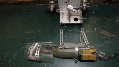
The router is attached with some perforated metal stripes when engraving glas. 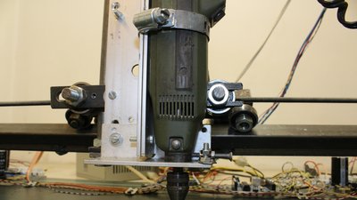
Same as before, the router is mounted on an aluminum angle using a metal ring, but now there is an additional fastening point at the bottom of the motor. Thats where commercially available brackets normally link the router with the mechanics - once more I am using the low tech version. 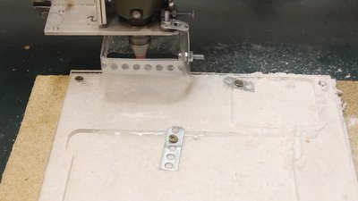
A "skirt" made of perforated metal stripes and a stripe of a plastic bag keeps the coolant or dust in place and your machine clean. Thanks to Luciano for that hint. Examples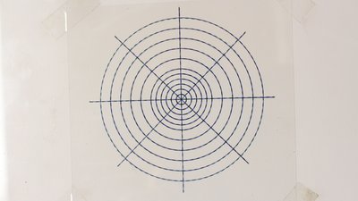
Test pattern, plotted with a ball pen. 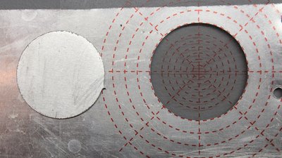
0.8mm Aluminum. Metal work wasn't part of the specification for this machine and the aluminum brings the mechanics to it's limits! 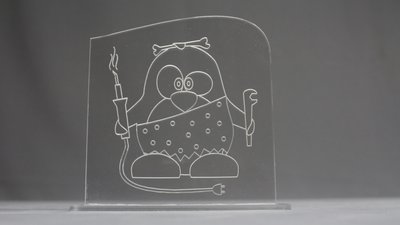
Acrylic plastics. 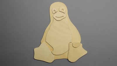
4mm poplar plywood. 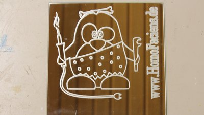
Envraving glas. Electronics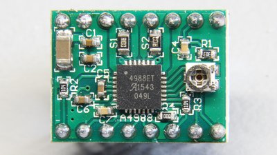
To get the maximum speed with those motors they are usually driven with constant current instead of constant voltage. I am using boards with A4988 chips which are cheap and can switch currents of up to 2A at up to 35V. 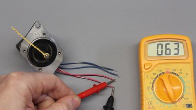
In order to connect the stepper motor to the driver board you need to know which pair of cables belongs to each phase. Switch your multimeter to continuity measurement to find those pairs. At this type, the red and the blue colored pairs are internally connected to a phase. 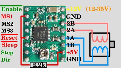
Phase 1 is connected to pin 1A and 1B, phase 2 runs to pin 2A and 2B. It doesn't matter what phase is connected with what pair of output terminals. Ground is connected to ground of the Arduino and also joined with ground of the voltage source of the motors. The voltage supply for the logic levels, sometimes marked with Vdd has to be connected to +5V of the Arduino. The supply voltage of the stepper motors must be in the range between 12 and 35V. I am using the 12V line of an old computer power supply. "Not reset" must be on HIGH level to activate the chip which is done by an external 2.2 kiloohms pull-up resistor (use a resistor between 1k and 10k). "Not enable" must be on LOW level. The board has an internal pull-down resistor, thus that pin is on LOW level by default. Nonetheless this pin is connected to a pin of the Arduino so that the motors can be disabled by software. "Not sleep" must be on HIGH level to activate the chip which is the default value caused by the internal pull-up resistor on the board. "Direction" and "Step" are connected to the microcontroller. MS1 to MS3 are used to adjust microstepping and all of those terminals have an internal pull-down resistor, thus they are on LOW level by default which means the motors are driven in full step mode. I am driving the motors with half steps, thus MS1 must be on HIGH level. 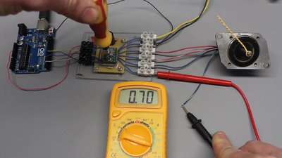
The phase current is adjusted by a tiny potentiometer. Dial the maximum current range of your multimeter - which is 10A at this type and switch it in series to a phase. I have adjusted all boards to 700mA which generates a torque that is sufficient to move all axes with ease. Furthermore that current is far from the limit values of the stepper motors as well as the driver boards, giving you a high reliability of the system. Never disconnect or connect the stepper motor from the driver board while the circuit is powered (as I did in the video)!!! 1.) Turn off power supply. 2.) Switch the multimeter in series to a phase. 3.) Turn on power supply and adjust the current to the desired value. 4.) Turn off power supply and reconnect the stepper motor to the driver board. 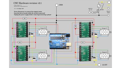
Schematics. Software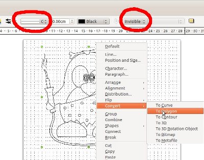
The software used to control the machine is written in C and it is running from the command line. With the menu you can choose the test pattern and set some variables. The supported vector format is "Scalable Vector Graphics (*.svg)" with some special things to note: No areas are drawn, only their outlines. All paths (also the outlines of an area) must be set to "Polygon". I have tested the functionality with graphics edited and exported as svg by Libre Office Draw: 1.) Draw graphics witth LibreOffice Draw. 2.) Press Strg + 'A' to mark all objects. 3.) Click on "Modify -> Convert -> To Polygon". 4.) Set line attributes to "Continuous" and to black color. 5.) Set Filling to "Invisible". 6.) Export as *.svg 7.) Copy the file to the subdirectory "pictures" in the installation folder of the CNC software. You can get the source code with some example vector files in the Download section. GRBLWith GRBL you can process G-code. I don't answer questions that are not related to this installation procedure of GRBL. Anything else can be found in the GRBL documentaion!.Load GRBL to the Arduino Uno using Ubuntu 14.04LTS: Install the Arduino IDE (version 1.1 or higher!): 1.)Open a terminal window with Alt + 'T' and type the commands: sudo apt-get update sudo apt-get install arduino 2.)Download GRBL Software and unpack with: wget -N https://github.com/grbl/grbl/archive/master.zip unzip master.zip 3.)Start Arduino IDE and import libraries: Click on "Sketch -> Import Library -> Add Library". Select the "grbl" folder inside the "grbl-master" folder and click "OK". After successful import you can find the software in the dropdown menue "File -> Examples -> grbl -> grblUpload". Click on Upload and wait until the process has ended successfully. Be sure the Arduino is connected to USB. 4.) Set machine parameters: With my stepper motors and 6mm threaded rods I get 200 steps per mm and the maximum speed is 120mm/minute. Open the terminal window of the Arduino IDE and set a baud rate of 115200baud and line ending to "Carriage return". Send the commands: $100=200 $101=200 $102=200 $110=120 $111=120 $112=120 $130=500 $131=500 $132=50 With the command: $$ you can list all machine parameters. Close the Arduino terminal window and the Arduino IDE. 5.)Install "Universal G-Code sender" (including JAVA 8 JDK!): sudo add-apt-repository ppa:webupd8team/java sudo apt-get update sudo apt-get install oracle-java8-installer sudo apt-get install maven wget -N https://github.com/winder/Universal-G-Code-Sender/archive/master.zip unzip master.zip 6.)Start "Universal G-Code sender": cd Universal-G-Code-Sender-master mvn exec:java -Dexec.mainClass="com.willwinder.universalgcodesender.MainWindow" You can find the example file "gnome-G-code.nc" in the subdirectory "pictures" of my software. How to create G-code using CAD software is your problem. I (currently) don't use any CAD programs! Frequently Asked Questions (FAQ)
<<< CNC v2.0 CNC v3.x series >>> News The Project Technology RoboSpatium Contribute Subject index Archives Download Responses Games Links Gadgets Contact Imprint |
||||||||||||||||||||||||||||||||||||
|
|