|
|
|
|
News The Project Technology RoboSpatium Contribute Subject index Download Responses Games Gadgets Contact HUINA forklift (R9) - ConstructionThe Video about the HUINA forklift conversionYou can buy the HUINA forklift on Gearbest. The base car, HUINA 1577
The dimensions of the forklift are approximately 50x17x30cm, the roll cage is composed of metal, the body consists of quality plastics and the tires are made of rubber. The build quality is very good, there are no sharp edges and the chassis of the vehicle is really sturdy. 
In the package there is the forklift with the remote control, an USB charger, three plastic pallets as well as the forks and a crane add-on made of metal.You can insert the forks and move them to adjust the width same as with a real forklift. The crane can be added at the center of the the lift mechanism. Four AA batteries that are not included in the package are needed for the remote control. The drive battery is placed in a box at the bottom of the forklift and it is composed of 6 Nickel-Cadmium cells with a total voltage of 7.2V and a capacity of 400mAh. Conversion to Rover R9Parts list:
USB camera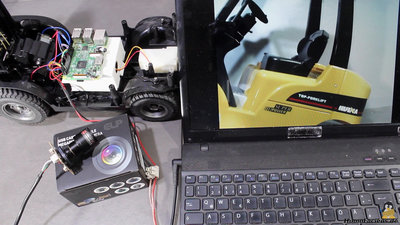
The great thing of the USB camera (you can buy it here Of course you can use any Linux compatible USB camera as well. Using the board electrinics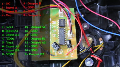
If you can't find a datasheet, you can start to guess and gauge what pin belongs to what function as demonstrated in the video: Turn the forklift off. Now you can find the output pins by switching your multimeter to continuity and put one probe on the motor while testing the pins with the second probe. You can hear that the motor of the lift is connected to pin 5 and 8 of the tiny chip. The drive motor is connected to pins 9, 12, 13 and 16 of the large chip which is obviously a double H bridge with the outputs switched in parallel. Now, Turn on the forklift and dial your multimeter to voltage detection with the black probe being connected to ground on the board, labeled with B-. You can identify the two input pins of each motor by activating the motors with the remote control. There is no voltage on the inputs while the motor is disabled. In forward direction there is a reading on one input pin while there is a voltage reading at the second input pin of the H bridge in reverse direction. We can identify pins 2, 3, 6 and 7 as inputs of the large chip and pin 2 and 3 at the tiny chip. 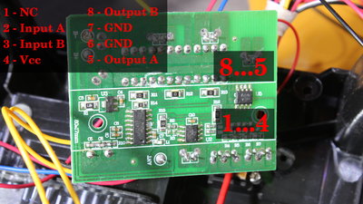
The H bridge for the steering motor is at the bottom side of the board and you can find the pin layout in the same way. 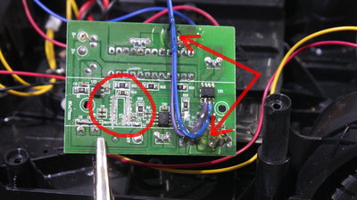
After identifying the input pins, you must remove the microcontroller of the radio control or else this device would work against the Raspberry Pi and so cause damage. I was using a Dremel to cut the pins off. After removing the chip you must check that none of the paths were shortened. Cables are soldered to the input pins of the H bridges in order to connect them to the Raspberry Pi. Especially the tiny chip at the bottom side was tricky to solder and you must avoid to bridge pins with solder. Check that out with your multimeter dialed to continuity. Some hot glue on the cables keeps mechanical load away from the solder points. Circuit layout/software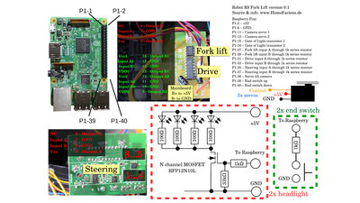
I am still working on the software. It will be available as download, soon. Same is for the 3D files. 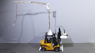
Electric power comes through two cables so that you can drive this robot 24hours a day and seven days a week. There is an anti twist mechanism on top of the forklift. Test driveR9 is placed in my RoboSpatium. That's where you can drive this forklift for free.News The Project Technology RoboSpatium Contribute Subject index Archives Download Responses Games Links Gadgets Contact Imprint |
|
|