|
|
|
|
News The Project Technology RoboSpatium Contribute Subject index Download Responses Games Gadgets Contact <<< Switching LEDs Simple Communication >>> LED matrixVideo about the working principle of a LED matrix.The video for the chapter originates from a collaboration with my sponsor NextPCB, from whom I received the circuit boards shown in the video. Have a click at the special offers from NextPCB for creating your own projects: Register to get $10 coupon and 20 Points: Special offer on NextPCB.com Fast & Free Shipping for PCBA order: Special offer on NextPCB.com PCB Boards 10pcs for Free: Special offer on NextPCB.com The 2nd video shows my NextPCB boards in detail OverviewIn this chapter you can read about:
Working principles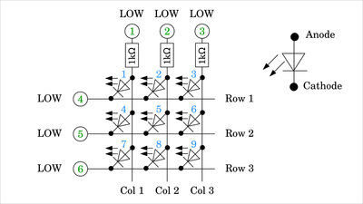
Here you can see a matrix of 9 LEDs. The three columns are connected to GPIOs 1, 2 and 3 via a 1kΩ resistor, the rows directly to GPIOs 4, 5 and 6. There is a LOW signal on all GPIOs , with which no voltage can be measured at any point in the matrix - all LEDs are switched off. 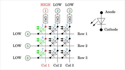
Now GPIO number 1 is set to HIGH signal, with which LEDs number 1, 4 and 7 are connected in forward direction and so start to light up. 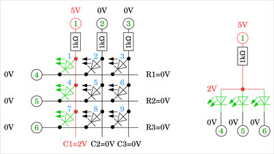
LOW signal, thus 0V, is on the cathodes (tip of the triangle with the dash at the diode symbol) of the three LEDs, the anodes (blunt side of the triangle) are connected to HIGH signal, i.e. 5V, at GPIO 1 via the 1kΩ resistor. Consequently the threshold voltage drops across the LEDs. This voltage depends on the type of LED used and is usually in the range of 1V to 3V. The threshold voltage can be measured at the anodes that are directly connected to one another. In the following, we assume that the logic level is 5V and the threshold voltage of the LEDs is 2V. The resistor at GPIO number 1 forms a voltage divider with the three LEDs, polarized in forward direction. The three LEDs are connected in parallel as can be seen in the equivalent circuit to the right of the matrix. 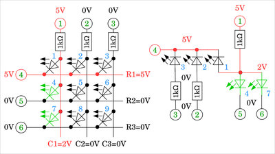
Now, GPIO number 4 is also set to HIGH level, which turns LED 1 OFF, while LEDs 4 and 7 remain ON. The equivalent circuit on the right shows that there is now 5V on the cathode of LED 1 - which is directly connected to GPIO 4 - and 2V on the anode, by what this diode is switched in reverse direction and no longer lights up. The cathodes of LEDs 2 and 3 are also directly connected to GPIO number 4, which means that 5V are applied here. The anode of LED 2 is connected to GPIO 2 via a series resistor, which also applies to the anode of LED3 and GPIO 3. Both are therefore at 0V level, with which LEDs 2 and 3 are switched in reverse direction and do not light up. 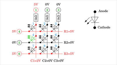
In order to finally switch off LED 7 and only keep LED 4 ON, GPIO 6 must also be switched to HIGH level, i.e. 5V. 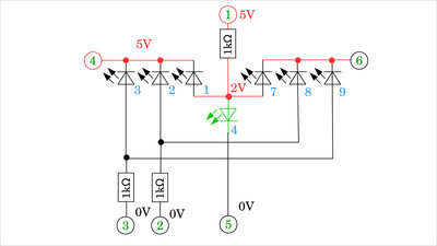
The equivalent circuit shows that only LED 4 is polarized in forward direction. LEDs 5 and 6 are not shown in the equivalent circuit diagram. 0V is present on both the anode and the cathode, which means that no current can flow through them. 
Same as as at the beginning, all LEDs are finally switched off when GPIO number 5 is also set to a HIGH signal. Nothing changes when switching GPIO number 1 to LOW. This is the better choice for the initial state of an LED matrix, because from this all LEDs remain switched off if GPIO number 1, 2 or 3 is now set to HIGH signal. 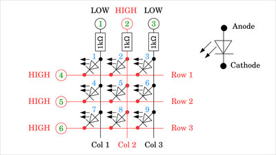
Here, this is the case for GPIO number 2. The LEDs in column 1 (LED 1, 4, 7) and column 3 (LED 3, 6, 9) are switched in reverse direction with 5V on the cathodes and 0V on the anodes. The diodes in column 3 (LEDs 2, 5, 8) have 5V applied to both the cathodes and the anodes, which means that no current can flow through any of the 3 LEDs. 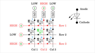
Not until one of the GPIOs number 4, 5 or 6 goes LOW a current flows through the network. Here, GPIO 5 is set to LOW, which means that a current exits GPIO number 2 and flows through the resistor and LED 5 into GPIO number 5. GPIO 2 is the current source, GPIO 5 is the current sink. 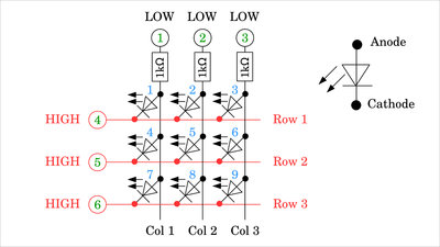
Before switching on the next LED, the initial state of Figure 7 should be restored. 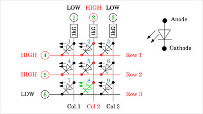
To switch on any LED, the GPIO of the corresponding column must be set to HIGH signal, first and the GPIO of the corresponding row must be set to LOW signal afterwards. Here these are column 2 (GPIO 2) and row 3 (GPIO 6), with which LED number 8 is switched on. Six GPIOs are sufficient to switch 9 LEDs individually. 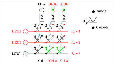
However, the LEDs cannot be switched independently: In Figures 2, 4 and 5 it can be seen that the LEDs of a column can either be switched on individually, in groups of two, or all three at once, for which column 1 must be set to HIGH signal and the respective row(s) to LOW. It works similarly when a row is switched to LOW. Depending on which column(s) are on HIGH signal, the corresponding LEDs light up. Here, this is the case for LEDs 8 and 9. 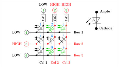
However, it is not possible, e.g. to only switch on the two LEDs number 3 and 8: For LED number 3, row 1 (GPIO 4) must be set to LOW and column 3 (GPIO 3) to HIGH. For LED number 8, row 3 (GPIO 6) must be set to LOW and column 2 (GPIO 2) to HIGH. This inevitably also turns on the two LEDs 2 and 9. 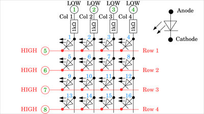
The LED matrix can be expanded as required. In a matrix of 4 columns and 4 rows, 8 GPIOs are needed to control 16 LEDs. For square matrices we get 25 LEDs with 10 GPIOs, 36 LEDs with 12 GPIOs, 42 LEDs with 14 LEDs and so on. 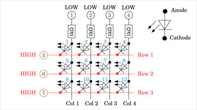
Unsymmetrical matrices are also possible composed of e.g. 3 rows and 4 columns, which results in 12 LEDs with 7 GPIOs needed. The ratio of LEDs to GPIOs is the most favorable for square matrices. Common Row Anode configuration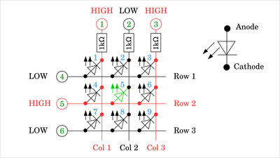
Up to now I have drawn the matrices in Common Row Cathode configuration. The cathodes of the LEDs in each row are directly connected to each other. In the drawing shown here it is a common row anode configuration, accordingly the LEDs in each row are connected on their anode side. In order to address an LED in this arrangement, a HIGH signal may only be present on the corresponding line, while the remaining lines are set to LOW signal. All columns except the column of the LED to be switched on must be set to HIGH signal. The signals are inverted compared to the Common Row Cathode configuration. Total current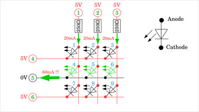
When calculating the resistance values needed, the maximum current of the GPIOs must be kept in mind! For the Arduino Uno these are e.g. 20mA per GPIO. According to Ohm's law, with a logic voltage of 5V we get: R = U / I = 5V / 0.02A = 250Ω Since there is also a drop in voltage across the LED, this forward voltage can be subtracted from the logic voltage. However for safety reasons I am using the higher value in the following. Note, that all LEDs in a row can be switched on simultaneously in the matrix, which means that a significantly higher current flows in parts of the network! The GPIOs of a column are connected to the LEDs via series resistors. Thus, the source current per column is definitely less than the maximum value. However, the rows are directly connected to the LEDs. If all the LEDs in a row are switched on at the same time, the sink current will add up to a value well above the maximum! To prevent this, the resistance values must be adjusted. The maximum current per GPIO is divided by the number of columns so that you get for a 3x3 matrix: R = N * U / I = 3 * 5V / 0.02A = 750Ω 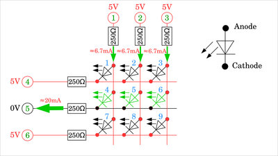
Plan "B" consists of connecting the rows to the LEDs via series resistors, too. With that, the lower resistance value of the previous calculation is sufficient and this does not have to be adjusted if the LED matrix is expanded. If the maximum brightness of the LEDs is needed, the signals of the GPIOs must be amplified e.g. by transistors, as can be read in the following chapters.
Plan "B" consists of connecting the rows to the LEDs via series resistors, too. With that, the lower resistance value of the previous calculation is sufficient and this does not have to be adjusted if the LED matrix is expanded. If the maximum brightness of the LEDs is needed, the signals of the GPIOs must be amplified e.g. by transistors, as can be read in the following chapters. 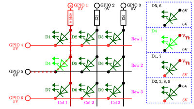
In the video I have demonstrated that the LEDs of a column shine brighter, the fewer are turned on. Or the other way round: The current through an LED is lower, the more LEDs are connected in parallel to one series resistor, which is true for the three LEDs in a column of the matrix shown here. Let's say the voltage drop across the LED is 2V at a logic level of 5V with a 500Ω series resitor. With that we get a voltage drop 0f 3V across the resistor and so with Ohm's Law a current of 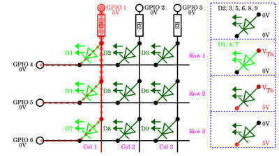
If all 3 LEDs of the column are activated, we get 3 resistors (=LEDs) switched in parallel, for what the total resistance is: RLED Total = 1 / (1/333Ω + 1/333Ω + 1/333Ω) = 27.5Ω The current flowing through the column at 5V is now: I = 5V / (500Ω + 27.5Ω) = 9.5mA Since that current is split into three branches, we get a current of only Multiplexing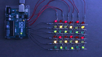
You can take advantage of the sluggishness of the human eye to give the impression that you can switch any combination of LEDs. As shown, the LEDs in each row can be controlled in any combination. The trick now is to drive the rows at a very high frequency from top to bottom and only switch on the desired LEDs. The active row is - based on a common row cathode configuration - switched to LOW signal, the columns of the LEDs to be activated are on HIGH signal. In order to build up the desired illusion, the matrix must be switched at a frequency of more than about 25Hz. With a 3x3 LED matrix, this means that a single row is active for only about: 1s / (25 * 3) ≈ 13ms before the next line is activated. In the photo it looks as if every second LED is permanently switched ON, which would not be possible without multiplexing. In truth, each line is only activated for about 1ms. Example circuit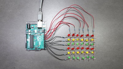
6x6 LED matrix with different colored LEDs: 12x 5mm LED Yellow 12x 5mm LED Green 12x 5mm LED Red 12resistors, 270Ω each I soldered the LED matrix here as a wire mesh to get it close to the circuit diagram. Make sure that no bare wires touch each other at the grid points! I put on small pieces of the insulation, which is quite fiddly. The circuit is easier to solder on a prototype board. Professional boardsIn the second video (see top on this page) I present my boards produced by NextPCB in moving pictures. Here are some additional details: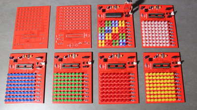
Boards from NextPCB with 64 LEDs each, populated with yellow, red, green, blue and white LEDs. The large version of an 8x8 matrix has an ATmega328P to control the LEDs. 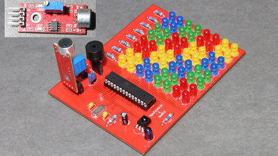
There is a built in infrared interface, composed of a TSOP4838 receiver module and an infrared LED. A second, accoustic interface is meant to be plugged into pin headers on the board - the receiver part is a microphone module that is available for the Arduino. It is essential to ensure that this module is not plugged in the wrong way round - there is no reverse polarity protection. Through jumpers you can chose if the analog or digital output of the microphone module is to be used. A buzzer that can be plugged into a second pin header row, serves as an acoustic sender - note the polarity of that component as well. Make sure that the modules are not plugged in the wrong way round - there is no reverse polarity protection! 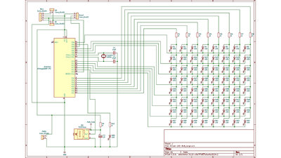
Circuit layout of the large 8x8 matrix, drawn with KiCad. Microcontroller: ATmega328P-PU R1-R8: 1kΩ R9: 100Ω R10: 390Ω Crystal: 16MHz C1, C2: 20pF C3: 4.7μF IR-Receiver: TSOP4843 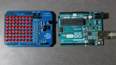
The second board is populated with 3mm LEDs and can be plugged onto an Arduino UNO. Here, too, an infrared interface is integrated and a microphone module and a passive buzzer can be attached. 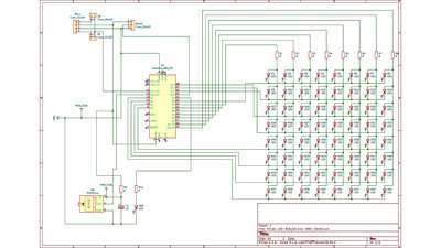
Circuit layout Arduino Shield, drawn with KiCad. Microcontroller: ATmega328P-PU R1-R8: 1kΩ R9: 100Ω R10: 390Ω Crystal: 16MHz C1, C2: 20pF C3: 4.7μF IR-Receiver: TSOP4843 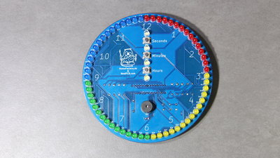
The LED clock has no interface - the time is set using 3 buttons on the front.The time is displayed similarly to an analog clock: The LED for the current hour lights up continuously, the one for the minute flashes asymmetrically every second and the LED displaying the seconds can be identified without further explanation. The LED circle is divided into four colors and the buzzer plays the melody of a well-known tower clock in London every quarter of an hour. 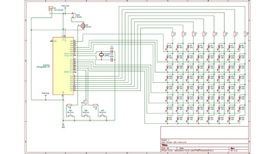
Circuit layout LED clock, drawn with KiCad. This board is also based on a 8x8 LED matrix. Microcontroller: ATmega328P-PU R1-R8: 1kΩ Crystal: 16MHz C1, C2: 20pF Transistor: BS170 DownloadsIn the download package (2.2MB) you will find the KiCad files, with which you can change my boards as you wish, and also the original * .zip files, with which you can order the boards from NextPCB. Also included are some Arduino program examples with which you can start your own experiments.Sourcing partsWhen buying components via the affiliate partner links I have listed in the table (or through the banners on my pages) you help to keep my my projects going - many thanks!Clicking on the links does not mean you have to buy - you can simply browse through the pages ;-) Of course, supporting my freely accessible educational platform without shopping but by making a donation or becoming a Patreon also works. Many thanks to everyone who already sent me an obol! If you know more parts that are good for building circuits shown on this page, please leave a comment.
<<< Switching LEDs Simple Communication >>> News The Project Technology RoboSpatium Contribute Subject index Archives Download Responses Games Links Gadgets Contact Imprint |
|
|