|
|
|
|
News The Project Technology RoboSpatium Contribute Subject index Download Responses Games Gadgets Contact CNC V3.2.2 - SIMATIC IOT2020 and bipolar stepper motorsElectronic components of CNC v3.2.2Short video about CNC v3.2.2Carving lenses with CNC v3.2.2About CNC v3.2.2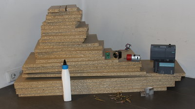
The development of CNC v3.2.2 is sponsored by Siemens and RS Components, the project was started for the Maker Faire on May 25-27, 2018 in Berlin. The frame of CNC v3.2.2 is mostly composed of 18mm chipboard as an option to the steel frame of CNC v3.2.1. The wooden frame is cheaper and simpler to build. The motors I am using are bipolar stepper motors to get an option for the electronics as well. The central brain is a SIMATIC IOT2020. I am running the "Apache" webserver on the IOT2020 to control the machine through a graphical user interface and a terminal program with implemented G code functionality. Parts listThis CNC originates from a cooperation with RS-Components which is why links in the table point to their online shop.
Mechanics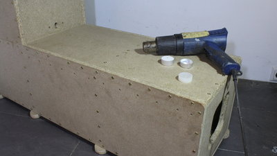
I have sealed the surface of the chipboard using candle wax and a hot air blower. 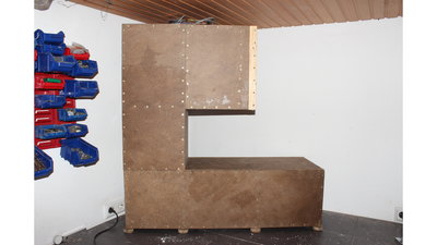
Approximately 25 tea lights were needed in total for the mechanics. At this side view you can see that parts 9 and 14 "widened" by 20x40mm roof battens. (Almost) all parts of the mechanics are made of 300mm chipboard stripes to make cutting easy. Of course you can cut the two parts having a width of 340mm. 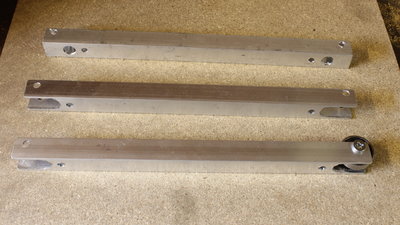
Some of the ball bearings are mounted at the ends of aluminum square tubes. To do so, I have drilled 12mm holes with a distance of 20mm from the edges and cut out the slots with a metal saw. Before that i have drilled 6mm holes for the axes of the ball bearings. The axes are at the bottom of the square tubes, not at the center. 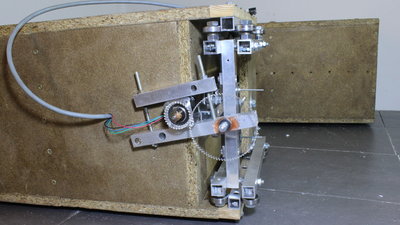
The mount of the motor of the Z axis uses two gear wheels. The motor could drive the threaded rod directly,... 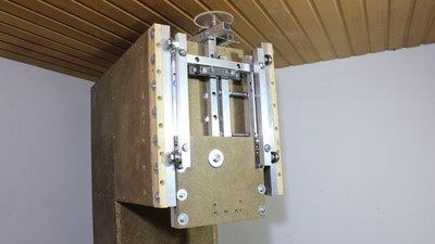
...however the low ceiling of my workshop doesn't allow that. 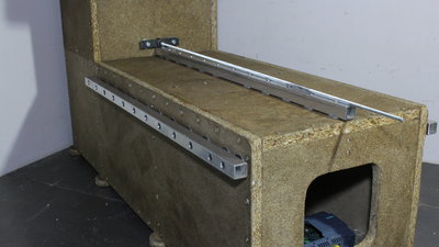
The guides of the Y axis. 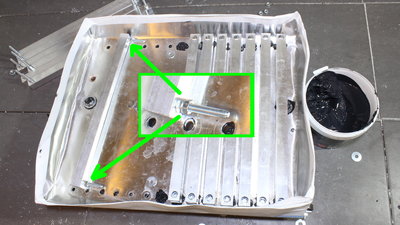
I have sealed all drill holes of the 0.5mm aluminum bowl using silicone and washers. Two stacked M6 nuts are used as spacers between the square tubes of the table and the bowl. 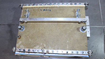
Bottom site of the X axis. 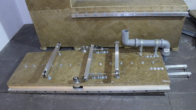
Bottom side of the Y axis. 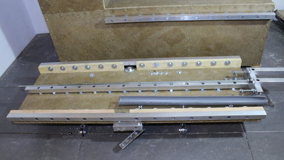
Top side of the Y axis. M10 nuts are used as spacers at the center guide of the X axis. 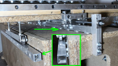
Two washers are used as spacers for the central guide of the X axis. M8 nuts and washers are the spacers used at the two side guides. 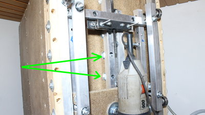
M10 nuts and washers are used as spacers for the central guide of the Z axis. 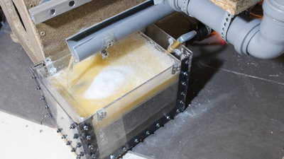
The reservoir of the coolant should have a capacity of at least 2L. A piece of foam serves as filter. 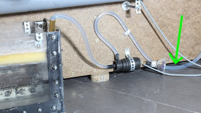
The pump of a winscreen washer drives the coolant flow. It's mounted on a deep point of the frame, because pressure difference is low at the intake side. The hose on the outtake must make a loop going below the level of the reservoir. Otherwise the coolant level drops below the pump whenever it is turned off and that type of pump doesn't work when it is dry. 
The motor of the Y axis is clamped by two pieces of wood. In a first attempt I was using weak stepper motors with a piece of rubber tube as connector between motor shaft and threaded rod. 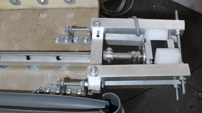
Mount of the X axis motor. With the more powerful motors I am now using rubber tubes with steel enforcements, made for household water installations. The foam keeps motor vibrations away from the frame and so reduced noise clearly. The motors are not connected tightly to the frame, but are able to move longitudinal and at right angles to the threaded rod. The mechanics of this CNC is designed in such a way that you don't have to cut all parts with highest precision. The motors form the "loose" end of the threaded rods. 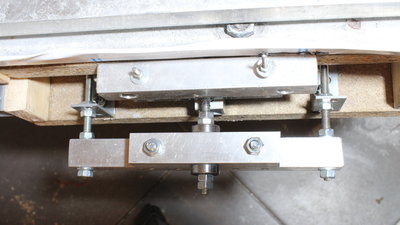
The fixed ends are connected with the mechanics through two ball bearings. Apply a bit of prestress to the bearings that are mounted on a square tube (x axis)... 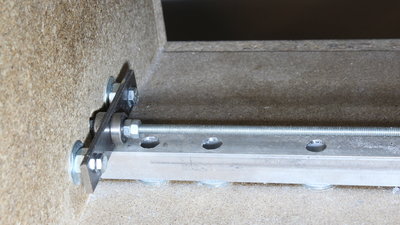
...or a 20x4mm flat steel bar. Not enough prestress results in unwanted backlash, too much prestress means too high friction - its up to you to find the best balance. 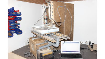
The frame is huge. CNC v3.2.2 would not fit in my workshop if it was just a couple of centimeters higher. Its also a heavy beast to move it to maker fairs... Electronics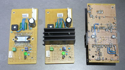
I am using ICs type LV8772 as motor drivers, all soldered on prototyping boards. The chips are manufactured with a distance of 1.78mm between the pins, but the boards I have in stock have a 2.54mm grid. In prototyping there is: What doesn't fit will be made to fit. By bending the pins and using pieces of copper wire, I managed to build the circuit on my boards. Only a few external components are needed to make the motor driver work, such as 6 capacitors, one is a large electrolytical type to smoothen the input voltage, two 220 milliohms 3 Watts resistors operating as current sensors and finally six 0.25 Watts resistors and a potentiometer. The green LED used to indicate the function of the IC is an extra I have implemented. Cooling power ICs is always a good idea, I am using aluminum heat sinks. The phase current is adjusted with the potentiometer on the board. The maximum phase current of the IC is 2.5A which is below the limit of the motor, however 1.3A are definitely enough to move the axes of the CNC with sufficient torque and speed. Avoid going to the limits to get a long life-time of your electronics. 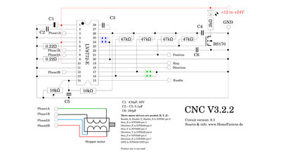
Circuit layout motor drivers: 3 boards in total are needed vor this CNC. SoftwareI am using a terminal program that can process gcode files. The interface is based on web server Apache, so that you can access the machine through a browser. The software is still a construction place...You have read all of this page? Well done, here is the download package of the build instruction. This machine is under construction. The documentation will grow as the machine does - stay tuned! News The Project Technology RoboSpatium Contribute Subject index Archives Download Responses Games Links Gadgets Contact Imprint |
||||||||||||||||||||||||||||||||||||||||||||||||||||||||||||||||||||||||||||||||||||||||||||||||||||||||||||||||||||||||||||||||||||||||||||||||
|
|