|
|
|
|
News The Project Technology RoboSpatium Contribute Subject index Download Responses Games Gadgets Contact <<< CNC T8 Ortur Laser Master 2 Pro >>> CNC 3018Pro from MosticsThe Video about the 3018Pro from MosticsYou can buy the 3018Pro from Mostics in their Amazon Store. You can request a coupon for special price offers by email. Just write to Mostics: sp.mostics@gmail.com Mechanics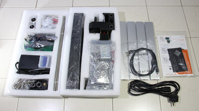
The 3018 Pro is delivered well packaged with all tools required for assembly and a printed, easy-to-understand instruction with many detailed drawings and photos. You don't need too high skills to put all parts together. I needed half a day for the assembly with most of the time passing by for making lots of photos during that process. The photos are available as download package(46MB) 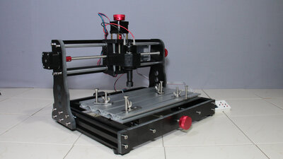
With a working area of 30x18x4cm the 3018pro can process standard board sizes while still being compact in the overall dimensions. The frame is composed of a mix of aluminum profiles and plastic parts and, with a size of 44x37x31 cm, fits on any workbench or desk. The stiffness of the frame is okay, but not perfect: The rather long lever from the round rods guiding the X-axis to the tip of the cutting tool causes the whole construction to twist visibly whenever you push a bit stronger. All in all the mechanics is okay for the price range and to be honest, the manufacturer does not advertise the 3018 Pro for metal working. I really like that all 3 axes can be operated manually using hand wheels. 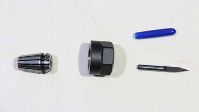
The cutting tool is mounted with an ER11 collet having an insert for 3.175mm shafts - that insert must first be snapped into the corresponding nut before the tool can be inserted. The CNC comes with V-bits, that can be used for engraving or cutting work. 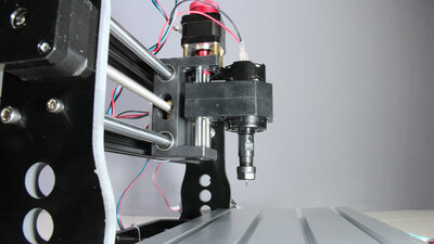
A DC motor with the ER11 collet mounted on the shaft is used as spindle drive. Its simple physics, that such a long lever can't grand good runout - with the naked eye you can see a slight wobble of the collet. Electronics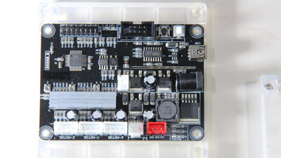
An Atmega328P, like the one installed on the Arduino Uno boards, is the central processing unit and grbl in version 1.1 runs on the chip. The ON / OFF switch on the circuit board at the back side of the frame is out of reach in an emergency situation, which is why it is advisable to use a switchable socket in front of the machine. 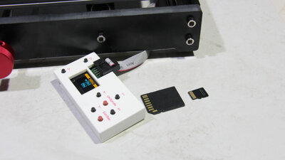
Data can be transferred to the CNC either via USB interface or via SD card and the remote control module that is available as an extra. 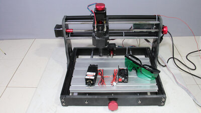
The laser module, that is available as an option, is connected to the electronics of the CNC with a separate control unit, for which only one additional cable is required. The laser replaces the spindle.The 3018Pro has no protective cover that prevents you from looking directly into the laser light, so wearing protective goggles is mandatory! Engraving Acrylic plastic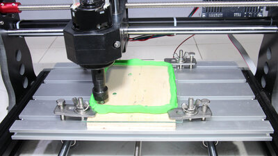
As a first test I have engraved my Tux mascot in a 2mm Acrylic plastic. When removing material with a milling cutter, frictional heat is generated. To prevent the plastic from melting, I made curbs out of modeling clay and filled the resulting basin with water. 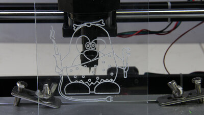
The outlines of my mascot are engraved by the 3018 Pro with a total depth of 0.6mm. The engraving is done after about 20 minutes - I really like the result of this first quick test. Isolation milling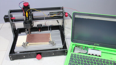
Now, let's come to the intended use, the isolation milling of circuit boards: The milled grooves should be as narrow as possible. The depth at which the tip of the V-bit dives into the copper-coated plate during the milling process should be constant. To achieve this, the height of the plate is measured at various points, using the milling cutter itself as sensor: Ground is connected to the copper plate and the V-bit is connected to a GPIO on a Raspberry Pi via the motor and a series resistor - seen here with my Pi-Top. Both, the scratches on the copper board,... 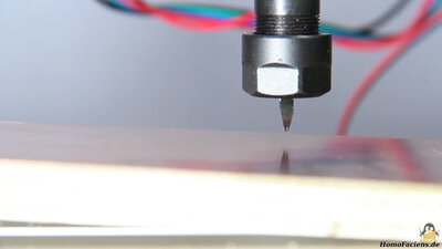
... as well as the broken tip of the V-bit indicate that error-free software does not exist - which is particularly true for early versions. When leveling the surface, the Z-axis moves down faster in a first pass, stops when it comes into contact with the copper plate and immediately moves back up half a millimeter. In the second pass, the Z-axis is lowered slowly. For my first experiments in isolation routing I was using a 20mm grid for leleving - that value can be changed in the script. 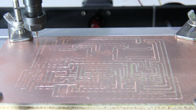
My first attempts to mill a circuit board have failed, but giving up is only for the fainthearted ... The solution I came up with is that the cut to the final depth is done in more than just one run. In the first pass, the copper coating is only scratched. It can be seen that the milling cutter dives into the material to different degrees. The boards I purchased for my first test are the cheapest I could get. The surface has visible ripples, which means that the cutter removes more or less only the tips of those ripples in the first pass. The height measurement of the surface with a grid of 20mm intervals, of course, did not record the ripples. It should also be taken into account that the copper coating is only 35 micrometers, which is 0.035mm thick and you cannot seriously expect that the mechanics of an inexpensive CNC is free from backlash of this magnitude. Overall, however, the 3018Pro meets the given coordinates with a sufficiently high degree of precision - the grooves are milled straight. The conversion of the Gerber files created with KiCAD to Gcode was done by the software pcb2gcode, my script reads the files generated in this way and adds some extra functions. After the first pass, the tracks are not yet isolated from the rest of the copper coating. 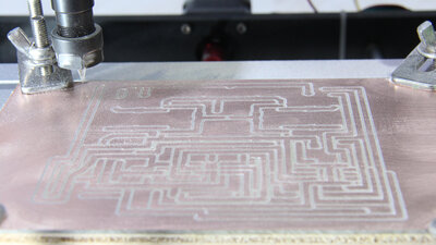
After each pass, the script asks whether the file should be processed again with the cutter being lowered a bit more. This question must be answered with "yes" for so long, until finally all the grooves are milled deep enough to get insulated traces all over the board. 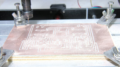
After that, the holes are drilled in the next pass: I use a standard 1mm drill that I had on stock. The second nut and the corresponding ER11 insert for the 1mm shaft also were in my workshop. The script first places holes in all four corners of the board - these are reference points for marking the top of the board. As already mentioned, the runout of the spindle is not perfect and the long, thin drill bends easily, which leads to the observed inaccuracy. All in all, however, the 124 holes were made with a sufficient precision. 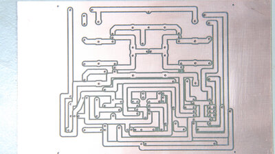
Finished bottom side: The milled grooves have really smooth edges, the V-bit cuts through the material without tearing off the edges of the copper coating. For the reasons mentioned, the holes are not as nicely centered as they should be, a good milling cutter should deliver better results. The copper around two holes was ripped off during drilling, but this is due to the fact that these are pins without a electrical connection to any path - this error is therefore irrelevant for the function of the board. I am happy with the result, the board will work as it came out of the machine, there is no need for any rework. 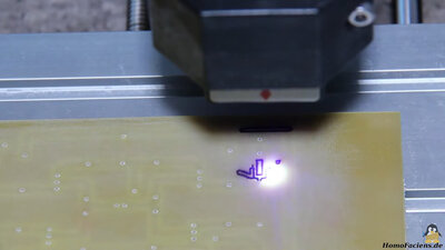
The next step is to label the top using the 5.5W laser module: In addition to the laser light, the resulting fumes are harmful to health - the process should take place near an open window or outdoors - I moved into my garage with the door open! Lasering the surface did not work the first time either: The problem is that the board material first melts and evaporates, but then carbonizes and so turns black. From this point on the material absorbs a lot more of the laser light, which suddenly burns a lot more plastic, resulting in an irregular engraving. Various tests with different laser powers have shown that the point from vaporization to charring is difficult to hit. To solve the problem, I don't work with a constant laser beam, but trigger short pulses, with a muvement of one tenth of a millimeter bnetween two laser bursts. In addition, I sanded the surface of the circuit board so that the laser light is better absorbed. 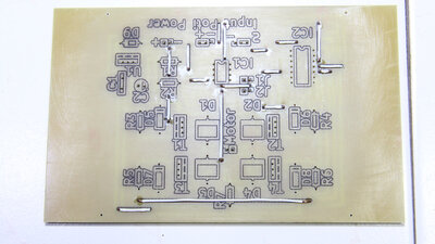
After removing the smoke traces with sandpaper, the lettering can be clearly read - the circuit board is finished and I am completely satisfied with this first result. 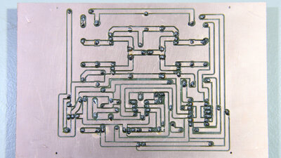
The fully solderes bottom side: 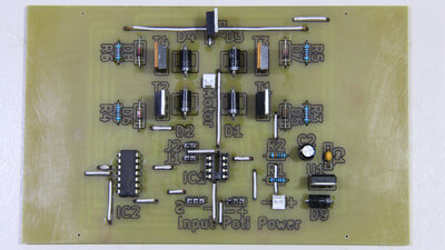
The fully populated top of the board: 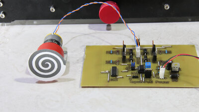
It is an H-bridge that is controlled by an ATtiny85 microcontroller. The microcontroller can receive commands via an interface in the form of pulse width signals or, as can be seen here, read in the voltage on a potentiometer. Thanks to the software running on the chip, the motor also works autonomously. My first attempt to manufacture a circuit board "out of the box" with the Mostics CNC 3018Pro can therefore be described as successful. SoftwareI created the Gerber files with KiCAD (https://kicad.org/) and converted them to Gcode with the program pcb2gcode (https://github.com/pcb2gcode/pcb2gcode). With the help of a self-written Python script, I milled and labeled the circuit board. This script is purely experimental and at the moment can only be read and used to some extent for users who are keen to experiment and with sufficient experience in programming Python! If you still want to take a look, here it is, but don't say I didn't warn you!<<< CNC T8 Ortur Laser Master 2 Pro >>> News The Project Technology RoboSpatium Contribute Subject index Archives Download Responses Games Links Gadgets Contact Imprint |
|
|