|
|
|
|
News The Project Technology RoboSpatium Contribute Subject index Download Responses Games Gadgets Contact <<< Operational amplifier RC circuit >>> Voltage dividerThe video about voltage dividersConstant resistance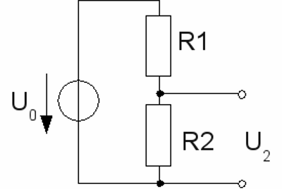
At the chapter about constant resistance networks, we got to know the theory of voltage dividers. Now I would like to introduce some practical benefits of those simple networks. Voltage dividers are very useful if you need a fixed fraction of the supply voltage for a special device in an electronic circuit. For example at the chapter about amplifying circuits, we applied a bias voltage to the base pin of a bipolar junction transistor. The bias voltage was around 0.67V, while the nominal voltage of the used battery was 12V. So the voltage ratio is What happens if the output voltage of the battery alters? The end of charge voltage of 12V lead acid batteries is 14V and you should stop uncharging them at a voltage of 11.2V, hence the voltage drop at R2 varies between 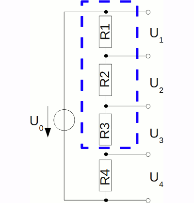
A voltage divider can be built by using more than just 2 resistors. Down below, a voltage of 0.75V at an input voltage of 12V is required, while the total resistance of the network should be 528Ω, hence a 33Ω and a 495Ω resistor should do the job, but you won't be able to purchase a 495Ω resistor. The solution of the problem is to use one 470Ω, one 15Ω and one 10Ω resistor instead (you won't be able to purchase a 25Ω resistor, too). The voltage drop at a single resistor is as follows: Rx = 12V * Rx / RTotal So we get 10.68V at R1, 0.34V at R2, 0.23V at R3 and finally 0.75V at R4. Output resistanceWhile using a voltage divider as a voltage source for a special device, you should keep the voltage shift in mind when connecting a load in parallel to one of the resistors. At the chapter about electronic switches we have learned that a base voltage of 0.75V at a BD135 is sufficient to turn an electric motor on. A voltage divider of a 2.7kΩ and a 180Ω resistance provides that voltage if no load is connected in parallel to R2. When connecting the transistor to the circuit, the voltage drop at R2 decreases to just 0.68V, which is insufficient to switch the electric motor. The resistance of the transistors emitter-base line is approximately 1800Ω.To obtain a more stable output voltage, the total resistance of the voltage divider has to be reduced. When using a 495Ω and a 33Ω resistor (see example above), the voltage drop at R2 is 0.75V without a load and 0.74V when connecting the transistor to the network. The drawback of reducing the total resistance is that most of the input voltage is wasted as heat. 256mW are dissipated at R1 and 17mW at R2, while just 375μW are drawn from the transistor. Potentiometer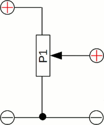
In principle, a potentiometer is an adjustable voltage divider. Usually they are constructed with a resistive element formed into an arc of a circle, a little less than a full turn. The voltage output at the sliding contact is between zero volts and the input voltage of the divider. A piece of a resistance wire with a clamp used as sliding contact can be used as a very simple construction of a linear potentiometer. The output voltage of the divider can be used as input value of a control circuit, hence potentiometers can be used as sensors for positioning purposes. Servos usually use single-turn potentiometers to control rotational movement. Accordingly the voltage output of a linear sliding potentiometer can be used to detect respectively adjust linear movement. 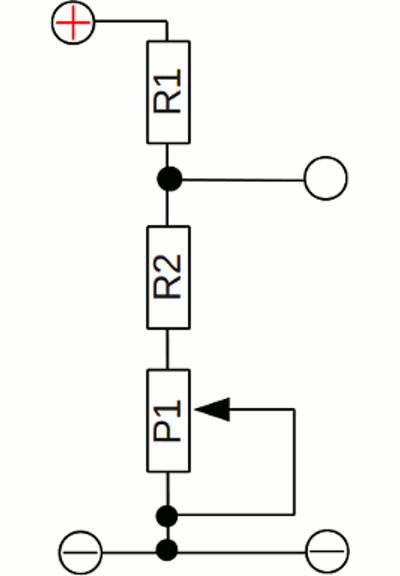
When shortening the middle pin connected internally to the sliding contact and one of the outer pins, a potentiometer turns into an adjustable resistor. This might be useful if a slightly varying output voltage is required for a special application. Adjusting a bias voltage of 0.6V to 0.7V with an input voltage of 12V is easy when using a 1kΩ potentiometer (P1) and a 100kΩ respectively 10kΩ constant resistor (R1, R2). H bridge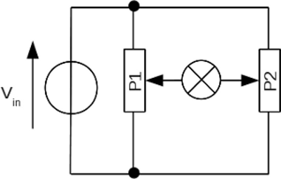
An H bridge is an electronic circuit that enables a voltage to be applied across a load in either direction. A very simple H bridge consists of two potentiometers with the load connected at the two sliding contacts. If the voltage output of potentiometer number one equals that of potentiometer number two (e. g. both are at their middle position), no voltage is applied to the load. 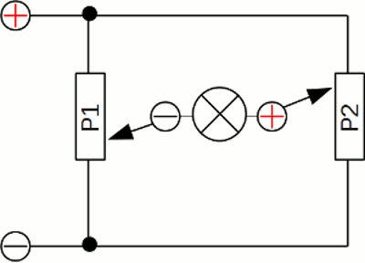
If the voltage output of potentiometer number two is more positive than that of potentiometer number one, the positive terminal is at the right side of the load. 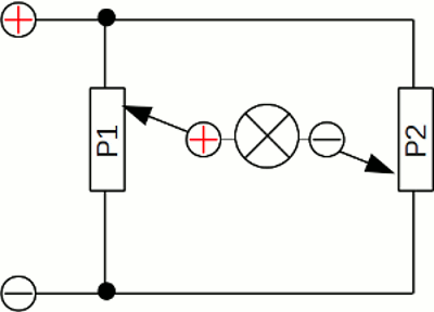
If the voltage output of potentiometer number two is less positive than that of potentiometer number one, the positive terminal is at the left side of the load. Diodes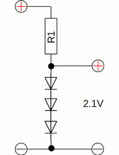
The current voltage characteristic of a semiconductor diode differs from that of an ohmic resistor. The resistance of a forward biased silicon diode is decreasing significantly above a voltage drop of approximately 0.6V. When replacing R2 by a forward biased diode, the voltage drop doesn't exceed 0.6V even if the input voltage is clearly higher. By switching two or more forward biased diodes in series, the voltage drop is a multiple of 0.6V. For example the resulting voltage drop is approximately 1.8V when using three diodes. 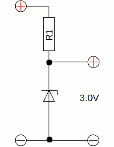
A special kind of diode is the zener diode. While used in forward polarity, the characteristics are identical to those of a normal diode. However a zener diode also allows a current to flow while it is reverse biased and the voltage is above a certain value known as the breakdown voltage or zener voltage. The voltage drop at a 3.0V zener diode exceeds that potential just slightly while it is reverse biased, hence the total current running through the voltage divider is affected by the resistance of R1 at input voltages above 3.0V. When connecting a load in parallel to the zener diode, almost no voltage shift can be observed as long as the resistance value of the load doesn't fall below a certain value: Rload = Uzener * R1 / (Utotal - Uzener) A voltage divider made of a constant resistor and a zener diode is therefore ideal for generating a reference voltage, or as a voltage stabilizer for low-current applications. Variable resistance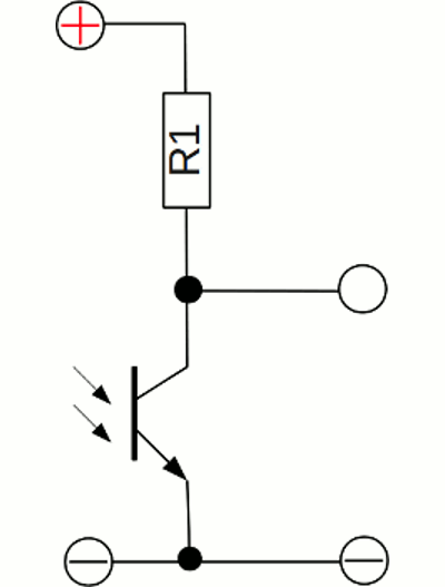
The resistance of some devices varies significantly with temperature or light. A voltage divider with one constant an one variable resistor can be used as sensor. The voltage drop at the variable resistor varies with the physical quantity to be observed. At the drawing, a photo transistor and a constant resistor are used to convert varying light intensity into a varying voltage drop. While the photo transistor gets illuminated, the voltage drop accross the device is decreasing. <<< Operational amplifier RC circuit >>> News The Project Technology RoboSpatium Contribute Subject index Archives Download Responses Games Links Gadgets Contact Imprint |
|
|