|
|
|
|
News The Project Technology RoboSpatium Contribute Subject index Download Responses Games Gadgets Contact ServosThe video about servosPosition control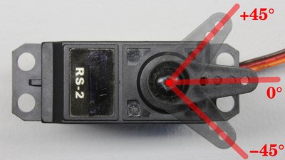
A servo is a device that produces motion accordant to a command signal from a control system. Usually an electric motor is used to create a mechanical force and the servomechanism rotates at a velocity that approximates the command signal. A sensor attached to the servomechanism reports the motor's actual status back to the control circuit of the motor. 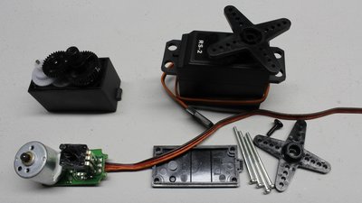
Disassembled RC servo: A potentiometer (bottom left of the photo) connected to the output shaft of the reduction gear operates as rotational sensor. Command signal
The position of servos used in small-scale robotics applications or in radio controlled vehicles, is usually set by a pulse-width signal. The base frequency of the control signal consists of a 50Hz pulse train with a duty cycle varying between 5% and 10%, determining the position of the servo. Most servos have a 90° rage of motion with a pulse length of 1ms according to an angle of -45°, 1.5ms according to the middle position (0°) and 2ms according to an angle of +45°. Different manufacturers servos behave slightly differently, thus the angle of rotation can be extended up to 180° when using pulses ranging from nearly 0ms to 3ms. Usually there are hard stops at the output shaft, limiting the angle rotation. To avoid damage, you should not drive a servo with pulse signals causing the motor to press against the hard stops. The motor will draw a high current whenever the rotation is blocked and the gear wheels might get destroyed if the torque of the servo is high enough. Some servos interpret "no pulse" as a pulse length of 0ms, hence these types start turning counterclockwise as far as they can whenever the control signal is turned off while the servo is still connected to the power supply. Some servos have a failsafe feature that powers down the motor if the servo stops receiving pulses or if the pulse length is above the maximum value. Servo driverAt the chapter about zur pulse-width modulation a circuit composed of an inverting Schmitt trigger and two diodes was introduced. By choosing appropriate values for the capacitor / resistor combination, the circuit can be used as servo tester: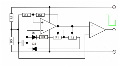
Quad op-amp = LM324 C1 = 0.1μF R1 = 47kΩ R2 = 12kΩ R3 = 16kΩ R4 = 2kΩ R5 = 1kΩ P1, P2 = 10kΩ The second operational amplifier decouples the signal of the servo tester from the oscillating circuit at the output of the first one, resulting in a higher signal quality. In the chapter about pulse-width modulation, a circuit composed of a non inverting Schmitt trigger, an integrator and an inverting Schmitt trigger was introduced. This circuit can be used as servo tester, generating an output signal with a base frequency of 50Hz and an adjustable pulse length between 0ms and 4ms: 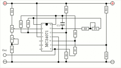
Quad op-amp = MC34071 (better) or LM324 (cheaper) C1 = 0.33μF P1, P3 = 10kΩ P2 = 1kΩ R1 = 13kΩ R2 = 27kΩ R3, R9 = 56kΩ R4 = 220kΩ R5, R6, R10, R11 = 27kΩ (or any value between 10kΩ and 100kΩ) R7 = 1MΩ R8 = 2.7kΩ With an oscilloscope you can adjust the base frequency of the output signal by turning P3. After that, turn P2 to the middle position and adjust a pulse length of 1.5ms by turning P1. If there is no oscilloscope available connect a servo to the circuit and turn P3 and P2 to their middle position. Now turn P1 until the lever of your servo is at its middle position. After this calibration procedure, the servo signal can be varied by turning P2. Motor controlThe pulse width signal has to be turned into a movement of the motor by the control circuit. The simple layout used in this chapter demonstrates the functionality: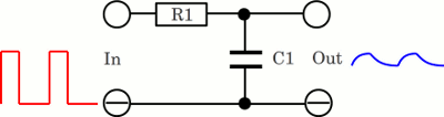
First of all, the pulse width signal has to be converted into a 0 to 0.5V DC signal using a low-pass filter. The capacitor is permanently charged respectively discharged by the pulse-width signal, thus the curve progression gets smoothened at the output of the filter. The smoothing effect translates the input signal into the average output voltage of the PWM signal. A disadvantage of this simple filter is the ripple at the output signal, which can't be removed completely, but made as small as possible. The higher the capacitance and the resistance of the filter, the lower the ripple. On the other hand, if the PWM signal is going to change rapidly, the voltage at the output of the low-pass filter is following faster, the smaller the capacitance respectively the resistance of the RC circuit becomes. The values of the RC filter are always a compromise between those contrary requirements. 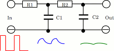
So the input signal is smoothened clearly at the output of a low-pass filter. What happens if another low-pass filter is connected to the output of the first circuit? Well, the signal gets smoothened even more. This arrangement is named second order low-pass. A high order low-pass is optimally suitable to convert the pulse-width signal into an appropriate DC voltage. 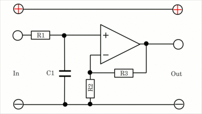
The output voltage of the low-pass filter varies between 0 and 0.5V at a pulse length ranging from 0ms to 2ms, considering a supply voltage of 5V. The DC voltage can be amplified by an operational amplifier with negative feedback. The required gain is 10, hence 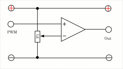
The motor of a servo is driven by an H-bridge. The motor must turn right (or left, depending on the polarity of the sensor), whenever the amplified DC voltage of the PWM signal is higher than the voltage output of the potentiometer operating as sensor. On the other hand the motor must turn left if the PWM signal is lower than the sensor output. A device suitable to control the H-bridge is a comparator. If the input voltage of the PWM signal is lower than that of the potentiometer, the output of the comparator equals zero volts and the motor is driven with a polarity turning the device anticlockwise. The polarity is swapped, whenever the voltage of the PWM signal exceeds that of the rotational sensor, by what the output signal of the comparator is brought HIGH. The output signal of the comparator is either 0V or it equals the positive supply voltage, thus, the motor connected to the H-bridge is always powered, turning clockwise or anticlockwise. 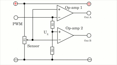
To get a third state with the motor being turned off, a window comparator can be used. Let's assume the DC voltage coming from the PWM signal is half the supply voltage and the output signal of the potentiometer is above that value. The signal at the non-inverting input of the upper op-amp is higher than that at the inverting input. The resulting output signal of the upper op-amp is HIGH. The situation is different at the lower op-amp: The output of the potentiometer is connected to the inverting input and the lower potential of the PWM signal is connected to the non-inverting input, hence the output state is LOW. The output state of the window comparator alters if the potential at the potentiometer pin drops slightly below that of the PWM signal: The output signal of the upper op-amp is brought LOW. Caused by the voltage divider composed of R1 and R2, just a fraction of the potential provided by the PWM signal is attached to the non-inverting input of the lower op-amp. As long as the output of the potentiometer is just slightly below that of the PWM signal, the potential at the non-inverting input of the lower op-amp is still lower than that at the inverting input, hence the output of the lower op-amp stays LOW. Not until the potential at the potentiometer pin drops below a certain value, the voltage at the inverting input is lower than that at the non-inverting input and the output of the lower op-amp is brought HIGH. If USensor > UPWM then op-amp 1 = HIGH and op-amp 2 = LOW If USensor < UPWM and USensor > UX then op-amp 1 = LOW and op-amp 2 = LOW If USensor < UX then op-amp 1 = LOW and op-amp 2 = HIGH For UX there is: 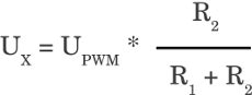 The supply voltage ranges from 5 to 12V (24V should be possible, but its not tested yet): 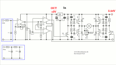
Op-amp - LM324 (chap) or MC34071 (better signal quality) C1 - 4.7μF C2, C3, C4, C5 - 1nF D1, D2, D3, D4, D5 - 1N4003 D6, D7, D8, D9 - SB1240 D10, D11 - LEDs (e.g. red and green) R1, R3 - 33kΩ R2 - 12kΩ R4, R5, 56 - 2.7kΩ R7, R8, R9, R10 - 47kΩ R11 - 470Ω P1, P2, P3 - 100kΩ P4 - 1kΩ T1, T3 - IRF9Z34N T2, T4 - IRLZ24N T5, T6 - 2N7000 Voltage regulator 5V - L4940V5 C6, C7 depend on the used voltage regulator! C6 - 0.1μF C7 - 22μF Instead of R1 and C1 you can use the second order low-pass: R1a, R1b - 220kΩ C1a, C1b - 0.33μF Before connecting the servo motor to the circuit, turn potentiometer number 1 and 3 to the middle position and potentiometer number 4 to the maximum voltage. The servo horn has also to be turned to the middle position manually. If the circuit is driven by a pulse-width signal of approximately 1.5ms, both LEDs should be turned off. Shifting the pulse-width in one direction lights up the green LED, while the red LED is turned on whenever the signal is shifted in the other direction. Adjust a pulse-width lighting up one of the LEDs barely. If the motor is connected to the H bridge, it should be powered by the H bridge just for a short span of time, turning the potentiometer in such a way that both LEDs are turned off. Swap the terminals of the electric motor if the servo starts turning with full power in the wrong direction. By turning potentiometer number 4, the maximum voltage output of the sensor and so the maximum angle of rotation at the highest duty cycle can be adjusted. Potentiometer number 3 adjusts the gain of the DC voltage caused by the pulse-width signal, thus it can be used to adjust the neutral position. One resistor at the voltage divider of the window comparator is replaced by a forward biased diode and a potentiometer switched in parallel to the device. The voltage drop across the diode is approximately 0.6V and it is independent from the DC voltage caused by the PWM signal. By turning potentiometer 2, the voltage range bringing both op-amps of the window comparator LOW can be adjusted. The smaller that "window" the closer the position of the servo lever to the set point. The motor starts oscillating around the set point if the window becomes too small because of the ripple at the DC signal of the PWM input. The precision of the simple control circuit described above is lower than that of commercially available servos. Usually the motor is driven by pulse width signals with the duty cycle getting larger the more the actual value of the servo lever differs from the set point. Furthermore the maximum current running through the motor is limited in case the servo mechanism is jamming and finally the motor is turned off whenever the pulse length of the control signal is outside a given range. Hacking servos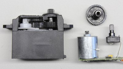
Servos can be modified to make them usable as very compact geared motors. This is done by removing the feedback sensor (potentiometer) and the hard stops at the output shaft. Without the stops and the potentiometer, the motor can spin continuously in either direction. When locking the potentiometer at its middle position and cutting the linkage between the pot wiper and the final gear, the sensor reading is kept at 0° independently from the true position of the servo horn. A pulse-width signal of 1ms (-45°) will cause the motor to spin with full power in one direction, while a pulse width of 2ms makes the motor start spinning in the opposite direction. The power delivered to the motor will decrease, the closer the PWM signal gets to 1.5ms and finally the motor stops spinning at a pulse width of (almost) exactly 1.5ms (0°). As mentioned above, some controllers shut down the motor at a pulse length of 0ms (=no pulse at all). The available range of drive speed depends on the motor driver circuit and varies between different manufacturer types. Instead of locking the potentiometer, the device can also be replaced by a fixed voltage divider with a resistance value of some kiloohm. Another modification deals with the electronics of a servo: The board controls a tiny electric motor, thus the maximum power output of the integrated H bridge isn't very high. To be able to control high power motors, an H bridge composed of power transistors is required. The precisely operating electronics of the servo board can be used to control a power H bridge. The input signal of the high power H bridge is generated by the output signal of the low power H bridge at the servo board. The signal is coming from the two cables usually running to the motor, which can not be directly attached to the inputs of our power H bridge. 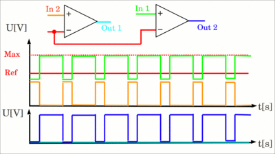
To be able to control the power H bridge by those signals, we need two comparators and a reference voltage somewhere between half and the total supply voltage. A half bridge is driven by a LOW signal, whenever the voltage at the related output of the servo board is below the reference voltage, which is 2/3 of the total supply voltage at the drawing shown here. Whenever the potential at one of the output pins exceeds the reference potential, the related half bridge is driven by a HIGH signal. 
Op-amp - LM324 (cheap) oder MC34071 (better output signal) C1, C2, C3, C4 - 1nF D1, D2, D3, D4 - 1N4003 D5, D6, D7, D8 - SB1240 D9, D10 - LEDs (e.g. red and green) R1 - 1kΩ R2, R3, R4 - 2kΩ R5, R6, R7, R8 - 47kΩ P1 - 5K - 100kΩ T1, T3 - IRF9Z34N T2, T4 - IRLZ24N T5, T6 - 2N7000 Voltage regulator 5V - L4940V5 C5, C6 depend on the used voltage regulator! C5 - 0.1μF C6 - 22μF There are no adjustments necessary to operate the circuit; just note the correct polarity of the electric motor: Attaching the motor to the H bridge starts with adjusting the homebuilt servo to its neutral position. Now drive the circuit with a pulse-width signal so that one of the LEDs is lighted up barely. When attaching the motor to the H bridge, it should start spinning just for a short span of time so that both LEDs are turned off. If the motor starts spinning with full power into the opposite direction, you must swap the polarity. Some high quality servos use brushless motors and these boards are NOT suitable for this kind of modification! News The Project Technology RoboSpatium Contribute Subject index Archives Download Responses Games Links Gadgets Contact Imprint |
|
|