|
|
|
|
News The Project Technology RoboSpatium Contribute Subject index Download Responses Games Gadgets Contact <<< Multivibrator Constant voltage >>> Pulse-width modulationThe video about pulse-width modulationPower control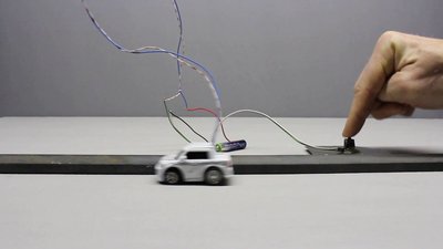
If your intention is to control the electric motor of a car, the simplest way to do this is using a switch in combination with a battery: While the switch is closed, the motor turns with the maximum power and while it is opened, the car stops. If you have ever driven a car you know that most of the time just a fraction of the engine power is required to move forward. Let's assume the car should cover a distance of 100m, that it would accelerate to its maximum speed in no time and that after closing the switch, 5 seconds are passing by until the vehicle reaches the finish line. That is equivalent to an average speed of 20m/s or 72km/h. So what if there is a speed limit of 50km/h? Now the car should cover the same distance in 7.2 seconds to meet the condition. To do so, you can turn on the motor for 2.5 seconds, turn it off for 2.2 seconds and turn it on for another 2.5 seconds. Now the car passes the finish line after exactly 7.2 seconds, but those way of driving is very rough and if there is a speed trap on the track, you still will have to pay some money. The solution of the problem is to turn the motor on/off multiple times. By turning the switch on for just 0.5 seconds, turning it off for 0.44 seconds and so on, the movement looks much smoother than before. When using intervals of 0.025 respectively 0.022 seconds, your eye (and so the speed trap) will recognize a car moving with 34km/h rather than noticing an object driving with maximum speed for 0.025 seconds each 0.047 seconds. Considering the inertia of the car, the movement becomes very smooth. Even the passengers won't recognize the single pulses of the motor control. The average speed of the car is controlled by turning the switch between battery and motor on and off at a fast pace. The longer the switch is on compared to the off periods, the higher the power supplied to the motor and so the average speed becomes. Those principle is called pulse-width modulation (PWM), or pulse-duration modulation (PDM). The proportion of "on" time to the regular interval is called duty cycle and is expressed in percent. 100% duty cycle means fully on while a lower value corresponds to lower power respectively lower speed at the example above. ElectronicsWe already have learned how to build a PWM circuit with a duty cycle of 50% at the chapter about multivibrators. By altering the circuit slightly, we can adjust the duty cycle of the output signal:
The resistor R3 was replaced by a potentiometer and two diodes were inserted. Now the charging current of the capacitor is running trough D1, while the discharging current is running through D2. Depending on the adjustment of the potentiometer P1, the resistance of the charging current - running through the upper branch of the circuit - is different from those of the discharging current - running through the lower branch. The switching frequency is the reciprocal value of the period ([9.4]): where is: ln(2) = 0.693147181 f - frequency R - resistance C - capacitance 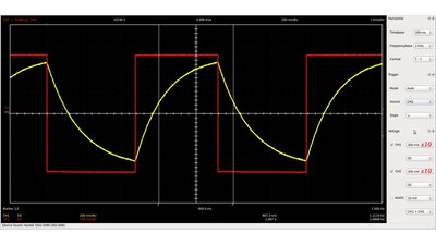
Oscillograph plot of a PWM signal with a 50% duty cycle, which is identical to the output signal of the astable multivibrator treated at the previous chapter. Red - output signal Yellow - voltage progression at the capacitor respectively the inverting input of the operational amplifier. The switching frequency is clearly lower than expected while using a 0.33μF capacitor and a 1MΩ resistor. The measured value for the periodical time is 0.92s while 0.23s are the result of the calculation. One explanation is the voltage drop at the forward biased diodes (approximately 0.6V) which results in a lower charge respectively discharging current of the capacitor. 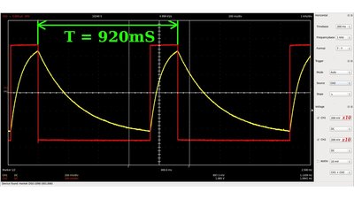
Duty cycle 20% 
Duty cycle 90% Whenever the duty cycle is altered, there is inevitably a slight variation in the switching frequency, because the two coupling networks at the inverting and non inverting input are both connected to the output of the operational amplifier. The switching frequency has to be faster than what would affect the load. For a motor control the switching frequency is usually a few kilohertz up to some then thousand kilohertz. Remember that there is a power loss in the switching device (the power transistor) whenever it's state is altered (see chapter switch for details), so there is an upper limit for the switching frequency. 
Sample circuit with a switching frequency of 330Hz: R1 = 47kΩ R2 = 12kΩ R4 = R5 = 2kΩ P1 = 1MΩ C1 = 1nF Op-amp e.g. LM324N T1 e.g. IRLZ24N for 5 - 24V, 10A operation. When replacing R1 by a 100kΩ potentiometer, the thresholds of the Schmitt trigger and so the frequency of the circuit can be adjusted. 
R1 = R3 = R4 = 56kΩ R5 = R9 = R10 = 220kΩ R6 = R7 = 100kΩ R8 = 12kΩ R11 = 1MΩ R12 = 33kΩ P1 = 10kΩ P2 = P3 = P4 = 100kΩ C1 = 0.33μF IC = MC34074P Quad Operational Amplifier This circuit is more complex and it is composed of three operational amplifiers. The left device is forming a non inverting Schmitt trigger, the middle one an integrator. The output signal of the middle op-amp is the input of the non inverting Schmitt trigger to the left, while the output of the Schmitt trigger is connected to the inverting input of the integrator via a resistor respectively potentiometer, resulting in a triangular shaped output voltage of both devices. Those signal is the input of the non inverting Schmitt trigger formed by the right operational amplifier. 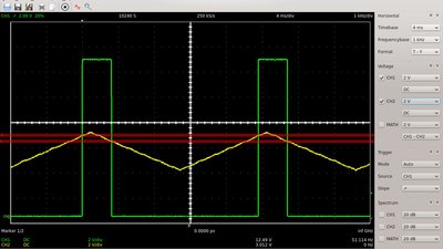
The level of the triangular voltage can be adjusted by potentiometer number 1. Whenever the peaks of the triangular voltage are crossing the upper respectively lower threshold of the Schmitt trigger, the output voltage tilts to either the positive or negative supply voltage of the operational amplifier. 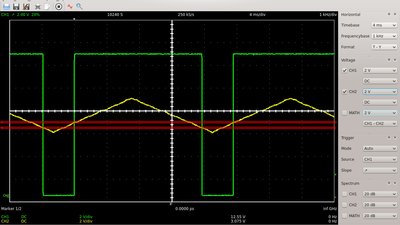
Hence the pulse width of the output signal is increasing with an increasing level of the triangular voltage. 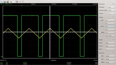
The frequency of the signal can be varied by adjusting potentiometer number 4. The lower the resistance value of the potentiometer, the faster the charging respectively discharging procedure of C1, hence the higher the frequency of the triangular voltage and so of the pulse-width signal. Frequency and duty cycle are generated by separate operational amplifiers, hence both parameters can be adjusted without affecting each other. The frequency of the output signal is more stable than those of the simple circuit. 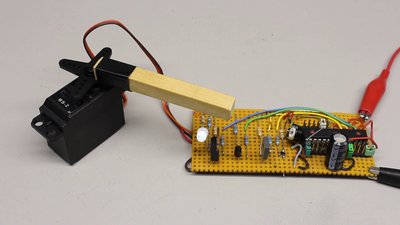
Whenever a high quality of the output signal at a wide frequency range is required, digital circuits are a good choice. Here an Atmega8A operates as the signal source of the circuit. The switching frequency can be varied precisely by software or by jumpers from a few Hertz up to some hundred thousand Hertz. 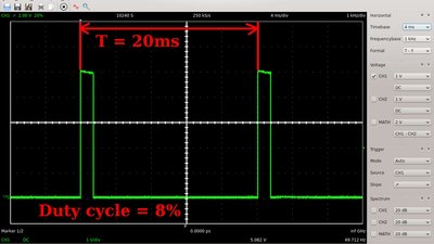
Servos are controlled by a special type of pulse-width signal: The frequency has to be adjusted to 50 Hertz while the duty cycle varies between 5 and 10%. In doing so, three wires between the sensor and the actuator are sufficient to control an element. In aviation those type of steering is called "fly-by-wire". Flyback diode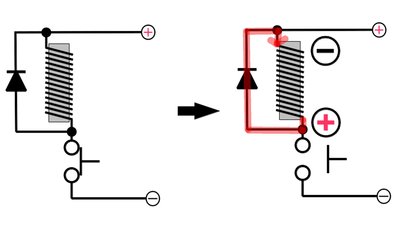
While switching inductors (e.g. an electric motor), high voltages are generated whenever the power transistor is turned off abruptly and those distortions are also increasing with increasing switching frequency. The abrupt change in resistance of the power transistor and so the change in current through the inductor induces a proportional voltage which opposes the change in current across the inductor. That voltage is added to the voltage drop across the transistor. The voltage peaks can be widely eliminated by a flyback diode, which is switched with reverse polarity in parallel to the inductive load. When the transistor is turned off, the diode becomes forward-biased relative to the inductor. The current running through the diode causes a negligible voltage drop of just 0.6V. Use high current diodes. The induced voltage spikes are short, but the stored magnetic field energy is high, thus a high current runs through the flyback diode. <<< Multivibrator Constant voltage >>> News The Project Technology RoboSpatium Contribute Subject index Archives Download Responses Games Links Gadgets Contact Imprint |
|
|