|
|
|
|
News The Project Technology RoboSpatium Contribute Subject index Download Responses Games Gadgets Contact <<< Bipolar junction transistor JFETs >>> Electrical properties of bipolar junction transistorsYou can find the tables of the recorded values at the column download.The video about bipolar junction transistorsPins
A bipolar junction transistor has usually three pin connectors: The emitter, base and collector pin. Two coupled current circuits are formed: The input circuit (Blue) running through the base pin and the output circuit (Green) running through the collector pin. Both circuits are connected via the emitter pin. The electric properties of the two circuits will be discovered at this chapter. Simple circuit
A very simple test circuit is used for the first series of measurement. A voltage divider consisting of three potentiometers and a one kiloohm resistor is used to attach a variable voltage to the base pin of the transistor. Resistors with a resistance value of 10Ω respectively 100Ω are soldered in parallel to two of the potentiometers. So these potentiometers are used for the fine tuning of the base voltage. A 390Ω resistor is connected between the collector pin and the positive terminal of the voltage source. Those resistor is called load resistor. A lead-acid battery with a nominal voltage of 12 V is used as voltage source. The detected voltage output of 12.38Volts is considered to be constant during the measurement series. Three digital multimeters are used to detect the base voltage, the base current and the voltage drop at the load resistor. Analysis of measurement series no 1Curve progression of base current versus base voltage:
The resulting curve progression is very similar to those of a forward biased semiconductor diode. Below 0.7 Volts the current running through the base pin is very low. Altering the base voltage at this area of the curve causes just a low variation of the current. Above 0.7 Volts, the gradient increases significantly. Altering the base voltage at this area of the curve causes a great varation of the current. There is indeed one single P/N junction between the base layer and the emitter of a transistor, which is switched to forward polarity (see chapter bipolar junction transistoren for details). With the help of the total voltage (=battery voltage), the voltage drop at the load resistor and the resistance value of this device, the resistance of the transistor's emitter collector line can be calculated:
RL - load resistor, RC - resistance emitter collector line, UL - voltage drop load resistor, UBat - battery voltage The curve progression of resistance versus base voltage can be drawn: 
By attaching a voltage at the base pin of a transistor, the resistance of the emitter collector line can be altered. The used digital multimeter can't detect a current below one microampere, which is why there are no values recorded below a base voltage of 0.6V. As you can see, the resistance value drops from 20,000Ω below one kiloohm while the base voltage increases from 0.6V to 0.7V. The voltage drop at the collector pin of the transistor was altered during the series of measurement, because of the altering resistance value. To be able to record reproducable values at the base pin, the voltage drop at the collector pin has to be kept at a constant level. Improved circuit
The load resistor is replaced by a PNP transistor. Thus we get a voltage divider consisting of two adjustable resistors by what we can align a constant voltage drop at the NPN transistor. The resistance of the NPN transistor is adjusted by attaching a positive voltage drop at the base pin like we did at the first measurement series. In contrast the resistance of the PNP transistor is adjusted by attaching a negative voltage drop between emitter and base pin. To limit the current running through the voltage divider, there is a filament lamp (L1) connected in series to the transistors. L2 is an additional voltage stabilizer inside of the control circuit. By using this test circuit, the voltage drop at the collector pin can be adjusted to a constant voltage between 2 and 8 Volt. As we saw at the first series of measurement, even a current below one mikroampere effects the electrical properties of the transistor clearly. Hence the current running through the base pin is recorded indirectly by measuring the voltage drop at an one kiloohm resistance. Analysis of measurement series no 2Curve progression of base current versus base voltage at collector voltages of 2V and 7V:
With increasing collector voltage, the current running through the base pin increases, too, because the electric fields of collector respectively base voltage are pointing into the same direction. The correlation between base current and base voltage is called input characteristic. Curve progression of collector current versus collector voltage with a constant base current of 50μA, 100μA respectively 200μA: 
Between 0 and approximately 1 Volt, the current running through the collector pin is increasing signifficantly, but the measurement setup doesn't facilitate the observation of this area accurately. Above 1 Volt there is an almost linear correlation between voltage and current. The slope of the curve increases with increasing base voltage. The resistance of the emitter-collector line is decreasing with increasing base current and it is increasing with increasing collector voltage. The correlation between collector current and collector voltage is called output characteristic. There is an almost linear correlation between collector current and base current: 
The collector current is approximately Beta times the base current: IC = β * IB Where is:IC - collector current, IB - base current, β - current gain The nondimensional parameter Beta marks the slope of the curve, which equals the current gain. Beta is increasing slightly with an increasing collector voltage. With the values recorded for the BD135 we get a current gain of approximately 130. The correlation between collector current and base current is called transfer characteristic. Curve progression of base voltage versus collector voltage with a constant base current of 50μA, 100μA respectively 200μA: 
Note that the measurement setup doesn't facilitate the observation of the area between 0 and 1V, but you can see the high slope at this area. Above 1V there is an almost linear correlation between base and collector voltage. While the collector voltage is increasing, a lower base voltage is sufficient to keep the base current on it's constant level. Like mentioned before, both electric fields are pointing into the same direction, hence the increasing collector voltage causes a higher base current if the base voltage would be kept on a constant level. The correlation between collector voltage and base voltage is called reaction characteristic. Four quadrant family
The curve progressions of input, output, transfer and reaction characteristic are often plotted in a four quadrant family. Reverse mode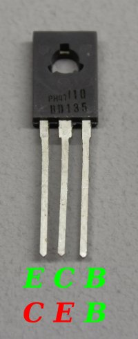 By interchanging the connections of emitter and collector pin, we can determine that bipolar junction transistors are not built symmetrically. The PN junction between base and emitter differs from those between base and collector. This arrangement is called reverse mode. In reverse mode, the maximum voltage of the reverse biased emitter-base junction is just some volts (below 8V in comparison to 45V at normal mode for the discovered BD135). The dopant concentration of the layers and the transistor's internal structure is usually optimized for forward-mode operation.
There is a considerable deviation of the input characteristic: 
The current gain is considerably lower: 
Limit values The limit values of a transistor have to be considered while using those devices.
 The maximum power dissipation, the maximum collector voltage and the maximum collector current are usually marked in the output curve of the data sheet.
<<< Bipolar junction transistor JFETs >>> News The Project Technology RoboSpatium Contribute Subject index Archives Download Responses Games Links Gadgets Contact Imprint |
|
|