|
|
|
|
News The Project Technology RoboSpatium Contribute Subject index Download Responses Games Gadgets Contact <<< Plotter CDROM Plotter from 3D printer >>> V plotterThe video about the V plotterSven's version is faster and more precisely: https://www.youtube.com/watch?v=a3AkIxpZkvM https://hackaday.io/post/47161 Mechanics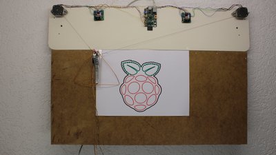
The V-plotter shown here uses a Raspberry Pi, two double H bridges to drive the motors, two stepper motors used to vary the cord length and finally one servo used to lift or lower the pen. The whole mechanism is mounted on a plate with the dimensions 94x20cm. The plate for the drawing area below is 90x43cm. The area covered by the pen is approximately 56x30cm. 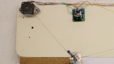
The cord is wrapped around the shaft of the stepper motors. The motors are mounted with their shafts pointing to the base plate to get the cords as closely as possible to the drawing board. 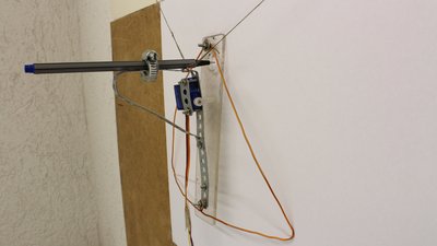
A clip is used to connect the pen to a stripe of perforated metal. That metal stripe in turn is connected to a stripe of acrylic plastic. A servo can bend the metal stripe and so lift or lower the pen. The triangular wire strap is used to stabilize the pen during operation. If the pen is lowered, the whole mechanism rests on three points on the drawing plane by what the pen is pulled perpendicularly over the board. Make that mechanism as light as possible to keep the forces acting on the cords low. That's why I am using a micro servo. 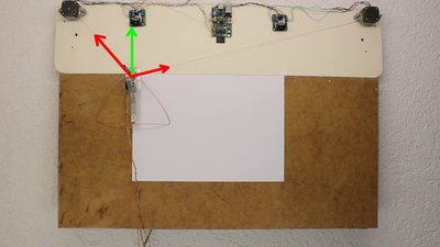
The closer the pen is to the base line, the higher the forces acting on the cords and so the larger the deviations caused by the flexibility. 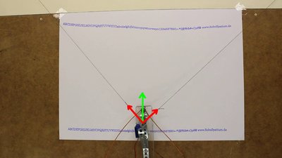
That's why lower text line is almost on a straight line. 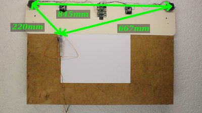
The software needs four parameters: The base length, thus the distance between the two stepper motors, the length of the two cords at the point of origin... 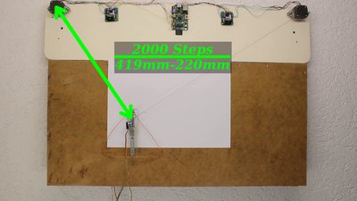
...and finally the number of steps a motor needs to move the pen for one millimeter. To get that value, one of the motors is turned for 2000 steps and the difference in cord length is metered. Those parameters have to be entered in the source code. 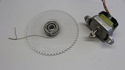
During plotting, the cords are wound respectively unwound by the stepper motors. The cords are wound in multiple layers on the shaft of a motor. Whenever a cord length is short, the diameter of motor shaft plus cord layers is maximal. If a cord length is at it's maximum, the diameter of the spool equals the diameter of the motor shaft. As a consequence, the move length of the pen with each step of a motor is lower, the longer the cord length becomes by what the calculation done by the software doesn't meet the reality, resulting in a visible error. With a larger diameter of the spools, that error is reduced. I have cut a gear from acrylic plastic with my CNC machine. 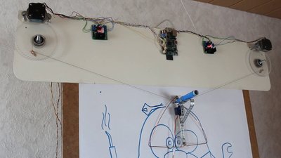
The cords are wound on a ball bearing with an outer diameter of 30mm. With a cord length of approximately 140cm, only some layers are needed to wind the cord on that larger spool. Furthermore the relative error per cord layer is lower than with a 5mm spool. 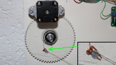
To get clearly defined points for the cord lengths during plotter operation, I am using small loops of copper wire. Maths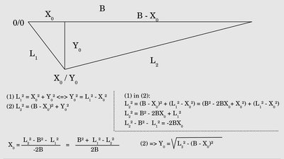
With the initial values for the cord lengths and the base length, the software can calculate X0 and Y0 at the point of origin. 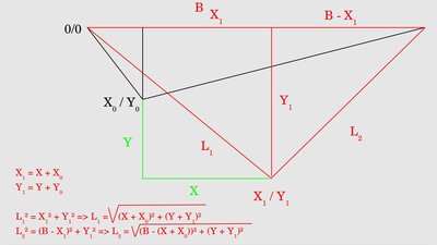
The X/Y values of the vector graphic have to be turned into cord lengths. Keep in mind that X0 and Y0 have to be added to X/Y of the paths. Electronics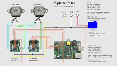
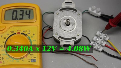
The stepper motors I am using draw a current of 340mA at 12V supply voltage, thus the electric input power is approximately 4W. With 5V the current drops to 150mA, the power is just 0.75W. The maximum current must be below the maximum current of the H bridges! The type printed on the motors is: Type KP4M2-217 1.8 Deg/Step 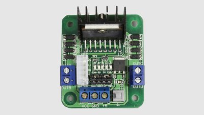
The H bridges are based on an L298N IC which are cheaply available in many types. The maximum continuous current is 2A. They heat up noticeably at currents above 1A. SoftwareThe software runs in command mode, thus you can login through ssh to operate the WLAN plotter. You can find the source code at the column Download.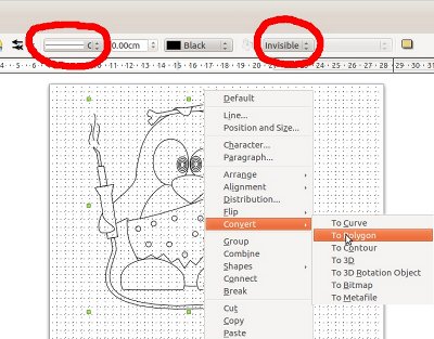
The supported vector format is "Scalable Vector Graphics (*.svg)" with some special things to note: No areas are drawn, only their outlines. All paths (also the outlines of an area) must be set to "Polygon". I have tested the functionality with graphics edited and exported as svg by Libre Office Draw. V-Plotter with ArduinoMorten has build a V-Plotter using an Arduino. Have a look at his instructions:http://pappmaskin.no/2016/08/pen-plotter-1 <<< Plotter CDROM Plotter from 3D printer >>> News The Project Technology RoboSpatium Contribute Subject index Archives Download Responses Games Links Gadgets Contact Imprint |
|
|