|
|
|
|
News The Project Technology RoboSpatium Contribute Subject index Download Responses Games Gadgets Contact <<< Python: USB Comunication Machine control via webserver >>> Robotic arm v1.0The video about robot arm v1.0Version 1.0
Version 1.0 of a robot arm was created as a weekend project. With the mechanics, I wanted to test the quality of special joints that I would like to use in a planned 3D printer with delta mechanics. The project is therefore a continuation of my ideas on adjustable joints. As a weekend project, I had to use what was in my workshop. For the electronic components and drive motors, I cannibalized a cheap CNC machine and built the mechanics out of roof battens and threaded rods. In terms of software (see below), the robotic arm fits very well into my series on "Physical Computing". Mechanics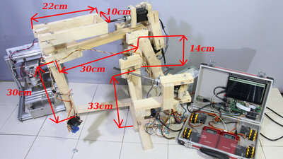
The dimensions of the robot arm were determined by the rule of thumb during assembly. Therefore, I cannot provide an exact building instructions. Instead I added some of the dimensions to this photo. It is not a high-tech industrial robot - let yourself be inspired by the roof batten construction and use your imagination if you are aiming for a replica. If you encounter unsolvable problems while trying to make your own copy of this robotic arm, leave a comment or send me an email. 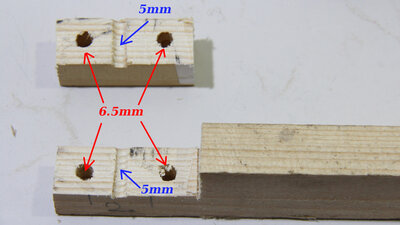
The joints are composed of pieces of 6mm threaded rod that rotate in adjustable bearings in the roof battens. First, three holes are drilled: The central hole has a diameter of 5mm and is therefore slightly smaller than the 6mm of the threaded rods and the two holes for adjusting the joint are slightly larger at 6.5mm. Now, a part of the roof batten is cut off. The joint rotates in the central hole and the backlash of the linkage can be adjusted using two screws in the larger holes. A bit of wax can be applied as lubricant with a hot air blower if you are looking for particularly smooth joints - I did not use any lubricant with this robot arm. Even if the bearing is adjusted very tightly, the joint can still move quite smoothly. 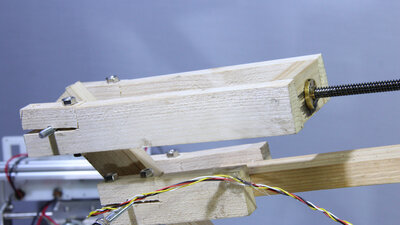
The joints are driven by the stepper motors and spindles of the cannibalized CNC machine. The brass nuts are attached to a subframe made of roof battens. 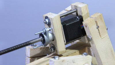
The same applies to the stepper motors and the ball bearings of the spindles. 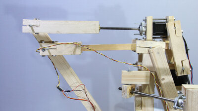
The two additional pivot points of the drive are necessary so that the lead screw and motor axis are always in line during the movement. The overall transmission ratio of the drive is ruled by the pitch of the spindles and the distance between the pivot point of the joint and the fastening point of the spindle. The closer it is to the pivot point, the faster the robot arm can move, the further away, the more precise and powerful the movement becomes. The joints can rotate a maximum of about 100 degrees. 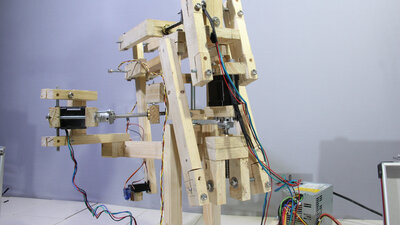
The shortest spindle is for lifting and lowering the robotic arm. 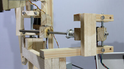
The joint rotating the robot arm is made of a piece of 10mm threaded rod to make the construction more sturdy. Here I have attached the brass nut of the drive in a more simple way without a subframe: Simpler also means a bit weaker, the version with two counter bearings is significantly stiffer. Since the force on this bearing is rather low, the simple version also works quite well. 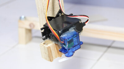
I attached two servos to the tip of the robot arm: The standard servo ensures that the gripper arm can be aligned in parallel to the ground, while the small microservo operates the gripper. 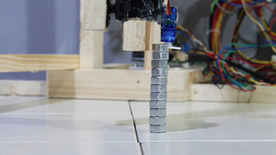
You can see the spindles wobbling, the spindles and stepper motors are not perfectly aligned. For pick and place tasks, this wobble doesn't really matter. It is important that one and the same point is hit exactly again when replaying a movement and that works even if the robot arm does not move linearly to the target point. The precision is definitely sufficient to stack 11 nuts for 8mm bolts. Parts listWhen buying components via the affiliate partner links I have listed in the table (or through the banners on my pages) you help to keep my my projects going - many thanks!Clicking on the links does not mean you have to buy - you can simply browse through the pages ;-) Of course, supporting my freely accessible educational platform without shopping but by making a donation or becoming a Patreon also works. Many thanks to everyone who already sent me an obol!
Electronics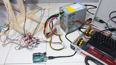
I have reused the electronics of the CNC as it was: It is an Arduino UNO with a CNC shield on top and the 12 and 5V lines of an old computer power supply are used to feed the arm with electricity. I connected the control lines of the two servos to the control pins for the milling motor. Software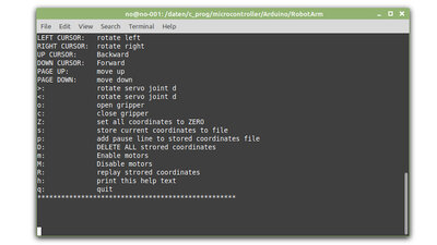
The Arduino no longer runs grbl, but a sketch written on the fly. A Python script (written for Linux) sends the control commands to the Arduino. Commands can either be entered via the keyboard or read from a text file. This text file is generated by directing the robot arm to the target points using the keyboard. By pressing "s", individual target points are stored in the text file, which can then be replayed as often as required by pressing "R". The Python script and the Arduino sketch are another example of communication between PC and Arduino via the USB interface. The software is available as download package. Any questions about this project? Feel free to leave a comment or send me a mail. <<< Python: USB Comunication Machine control via webserver >>> News The Project Technology RoboSpatium Contribute Subject index Archives Download Responses Games Links Gadgets Contact Imprint |
|
|