|
|
|
|
News The Project Technology RoboSpatium Contribute Subject index Download Responses Games Gadgets Contact <<< Ping Pong Plotter EDM: Mikroskop >>> Electrical Discharge Machining: IntroduktionThe video about the first EDM setupAbout the machine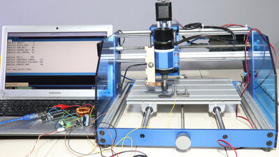
Here you can see my first, very experimental test setup of an Electrical Discharge Machine (EDM). A cheap CNC machine, which I have presented in detail on my 2nd project "How Open Is This Gadget?", is used as the mechanical part. 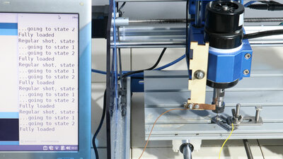
The only mechanical modifications I have made is adding a sliding contact to the tool holder of the milling motor and electrically isolating that motor from the rest of the mechanics with a layer of adhesive tape. Ground of the circuit is connected to this sliding contact. The +30V line leads to the workpiece holder via a screw and then to the workpiece. 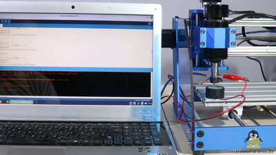
The firmware - grbl is installed out of the box - has been replaced by a few lines of code I wrote myself - I showed how to do this in a previous chapter. Working principle, short version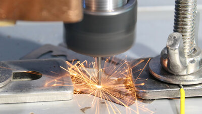
How does spark erosion work? Well, the drill is slowly brought near to the surface of the razor blade. In the electric circuit, composed of the charged electrolytic capacitor, the copper wires, the chuck and the drill bit, as well as the air between the drill tip and the razor blade, the latter has by far the highest resistance. Almost no current flows out of the capacitor. However, if the air gap becomes very small, a spark will jump over at some point, before the drill touches the razor blade. There is a lot to say about the process of spark formation, which I will explain in more detail in a later chapter - I already have a video on electrostatics on offer. The short version is: spark is a plasma, plasma is a very good conductor, and plasma is so hot that parts of the razor blade melt or even vaporize. As a result, a tiny bit of material is removed from the razor blade in a process named erosion. So do we keep the plasma burning until the hole is drilled to the desired depth? Unfortunately, it's not that simple - I won't explain the reasons in this video, but the plasma has to be extinguished again. On the one hand, this happens because the electrolytic capacitor discharges, which reduces the output voltage, and on the other hand, because the drill bit is lifted again. At some point the electric field between the drill bit and the razor blade becomes too weak so that the plasma breaks down. The process now starts from the beginning: The capacitor is charged again and the drill is lowered. More material is removed with each cycle until the razor blade is pierced by the drill at some point. My experimental setup works - in principle. 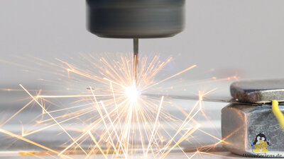
The drill penetrates a very hard metal almost without contact, which it only has scratched a little in the classic way. While drilling another hole, the razor blade is only clamped at one end to show that the drill bit just strokes the steel slightly every now and than during the process. Electronics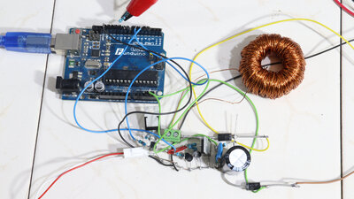
The 30V are generated from an input voltage of not quite 12V by a very quick and dirty soldered step-up converter. The core components of the circuit are an electrolytic capacitor that is charged to the output voltage, a self-wound toroidal coil, which increases the input voltage to the desired value via induction voltage when being switched on and off, an N-channel MOSFET that is used to control the current flow through the coil and a diode, which causes the higher output voltage to be isolated from the lower input voltage. The switching on and off of the MOSFET and thus the coil current is done by a microcontroller board with an ATmega328P chip. The firmware also consists of just a few lines of code that make sure that the capacitor is only charged to the intended output voltage. A signal can be output to the CNC machine via a pin, which indicates whether the output voltage has been reached or not. 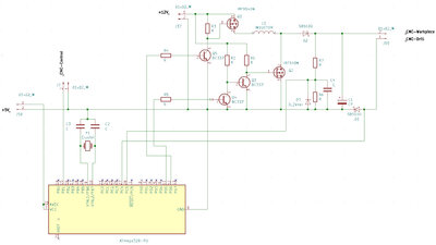
Circuit diagram of the very experimental step-up converter. The circuit is only recommended for those of you that are extremely keen to experiment! C1 = 2200μF, 50V C4 = 10nF Q1 = IRF9540N Q2 = IRF540N Q3-5 = BC337 D1,2 = SB5100 D3 = 4.5V Zener R1-5 = 1.5kΩ R6 = 5.1kΩ R7 = 100kΩ Software / DownloadThe setup in this chapter is extremely experimental in nature. I'm offering the schematic and the firmware I've written Quick & Dirty as a download package, but it's only for people who really know how to do coding with an Arduino and what a step-up converter is.<<< Ping Pong Plotter EDM: Mikroskop >>> News The Project Technology RoboSpatium Contribute Subject index Archives Download Responses Games Links Gadgets Contact Imprint |
|
|