|
|
|
|
News The Project Technology RoboSpatium Contribute Subject index Download Responses Games Gadgets Contact <<< EDM: Active Hammer (1) EDM: Welding inverter CNC (1) >>> EDM: 'Active Hammer', Part 2The video about engraving with an 'Active Hammer', Part 2'Active Hammer', Version 2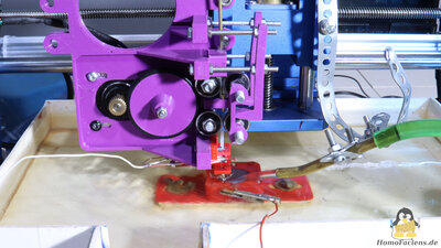
In the second chapter about my Active Hammer I would like to explain what changes I have made to the mechanics and then demonstrate how well it now works. 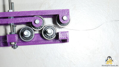
The failure comes first: In the first chapter I told that I wanted to implement a mechanism for straightening the electrode wire into the mechanics. I tried that, but had no real success. Such mechanisms work with 4 or 5 rollers or fixed cylinders as follows: The wire is first bent in one direction in order to have a defined radius. After that the wire is bent back until it is straight. My idea was to simply drive two of the rollers and thus combine wire feeding and wire straightening with the 4 rollers. But that didn't work because the 0.2mm tungsten wire came out of the mechanism in a corkscrew shape. Such wire straighteners typically work by pulling the wire through the mechanism. If the rollers themselves are converted into drives, the wire rotates in the mechanism due to the lack of wire tension, creating the corkscrew shape. Another problem is that when used as an "active hammer" the wire not only moves forward, but also back again during operation. Yeeees, I could probably make it work somehow, but that would result in a too complicated design while the intention of this series is to create a simple mechanism for spark erosion. Simple means: I straighten a piece of wire using a mechanism without rollers that came out of my 3D printer and then fumble the straightened wire into the mechanism - that works well enough. 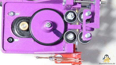
The 4 rollers are now arranged differently and only function as a wire feeder. Two of the ball bearings type 625 are driven by the stepper motor via a 40mm pulley whith a rubber ring on the circumference. I attached the toothed wheel of an extruder to the shaft of the stepper motor so that the drive works reliably. Two more bearings of the same type are pressed onto the two driven ball bearings - the electrode wire runs between them. With the plastic arms the ball bearings are pressed on the wire with almost constant force. By using two pairs of ball bearings, the force acting on the wire is reduced while there is enough friction to move the wire. 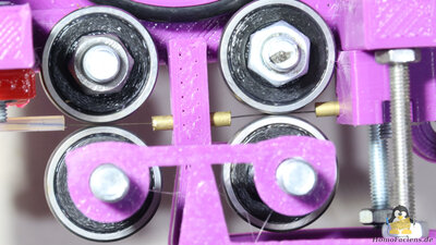
Three guides ensure that the wire stays in position between the ball bearings. 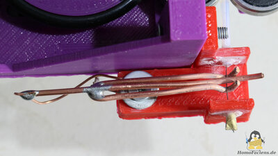
I spent most efforts in designing the contact point of the supply voltage with the electrode wire: This sliding contact consists of three copper tips that are clamped to the wire. Two of the tips are bent so that the clamp cannot slip off the electrode wire. This "sliding contact" actually hardly slides at all during the eroding process and that is the biggest trick of the arrangement: The copper gripper is attached to the frame via a flexible copper wire and can therefore move quite freely. If the electrode wire is moved upwards during the erosion process, the gripper move with the wire and therefore doesn't slide. The same applies to the downward movement, only the extra bit of downward movement caused by the electrode wear leads to a short sliding of the gripper. Virtually no sliding or grinding means that virtually no unwanted spark erosion occurs at this point. Furthermore, the distance between the gripper and the tip of the wire is quite short, which means that the resistance of the electrode wire in the circuit is kept as small as possible. Known issues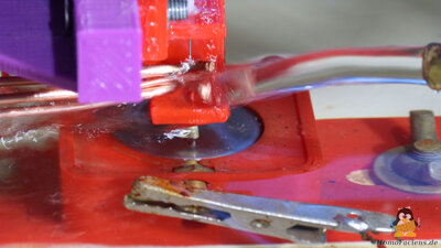
When engraving with a wire that is only 0.2mm thick, it becomes very hot, especially when operating with 12V. To prevent burnout, the jet of cooling water can be directed at the area with the contact gripper. However, then the electrode wire welds to the workpiece for a short time. To ensure sufficient cooling, the "Active Hammer" should be immersed in the cooling water up to the contact gripper and a strong jet of coolant should be directed onto the workpiece surface. HomoFaciens Coin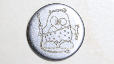
The engraving seen here was carried out with 12V and the coolant jet onto the contact gripper. Therefore, the electrode wire sometimes welded to the workpiece, which can be recognized by broken lines and small deformations. 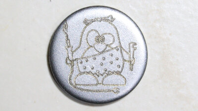
In the second experiment, a stronger jet of water was directed at the tip of the electrode wire, which prevented welding to the workpiece. The "coin" has a diameter of 20mm, the graphic is 15x16mm small. The time stamp of production is engraved on the back with a digit height of 2.2mm. Engraving was done using 0.2mm tungsten wire as an electrode. If you would like to purchase such a "HomoFaciens Coin" to get an own impression of how good the engraving is: You can support me financially in my experiments and receive a "coin" like this as a thank you for donations of €15 or more (don't forget to mail me your postal address if you want a coin). DownloadsI have designed the files with OpenSCAD. The scad file as well as all parts as STL files and the Arduino sketch are available as download package. I used PET-G to print the parts.<<< EDM: Active Hammer (1) EDM: Welding inverter CNC (1) >>> News The Project Technology RoboSpatium Contribute Subject index Archives Download Responses Games Links Gadgets Contact Imprint |
|
|