|
|
|
|
News The Project Technology RoboSpatium Contribute Subject index Download Responses Games Gadgets Contact <<< Imprint ...to be continued. >>> 3D printer Artillery Sidewinder X2The video about the Artillery Sidewinder X2Get the Artillery Sidewinder X2 on Geekbuying.com. Special price with Coupon code: NNNHOMEFACIENSDE The printer ships without filament, so add spools of 1.75mm filament to your order. About the printer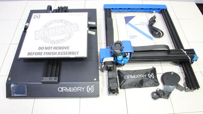
The printer ships almost completely assembled. Only the frame has to be screwed on the base, the holder for the filament spools must be screwed on and four plugs have to be connected to finish the assembly of the printer. 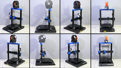
This 3D printer has a work area of 30x30x40cm and is therefore suitable for large prints. The firmware is based on Marlin and the manufacturer fulfills the GPL license by publishing the modified source code. There is a link to the corresponding Github page directly in the download area of Artillery3D - that's exactly how it should be. With that, anyone who likes to upgrade or retrofit the Sidewinder X2 in an unconventional way can get the full potential of the mechanics and electronics. Closed source devices will no longer enter my workshop! The Artillery Sidewinder X2 is a 3D printer just the way I like it: The mechanics is robust, all cables are neatly laid and the device worked without any problems during the tests, very quickly and quietly. There is no frippery, the printer has everything that is needed for printing in really good quality and nothing else! Electronics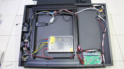
The electronic components are located in the base of the printer: After removing the cover plate it can be seen that the wiring looks tidy and the plug connections are locked in place with hot glue. 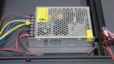
The power supply unit has an output voltage of 24V at a maximum of 8.5A, which corresponds to about 200W. 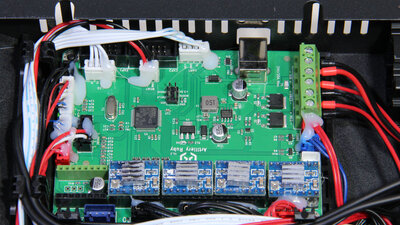
The four stepper motor drivers are plugged onto the main board - that's how I like it, because a driver can easily be replaced in the event of a defect. The Marlin firmware runs on an ARM processor type STM32. 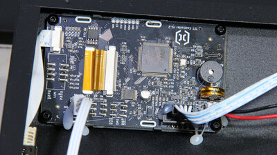
A second STM32 processor is located on the board with the touchscreen. This board also contains the connections for the USB stick and the micro SD card reader, via which the print data can be read. Mechanics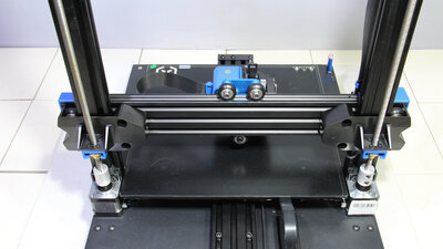
The Z-axis is guided along two 40x20mm extruded aluminum bars and driven by two stepper motors via spindles. 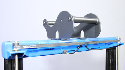
The two spindles are linked at the upper end by a timing belt. This prevents the two spindles from moving asynchronously when the stepper motors are switched off. With that, the height of the X-axis above the print bed never has to be readjusted. 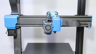
The X-axis moves along extruded aluminum with the dimensions 50x20mm, also guided by plastic rollers with ball bearings. The ribbon cable running to the extruder is attached to the bar of the X-axis - there is no tangled cable anywhere on the device. 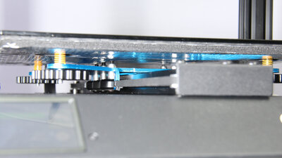
The print bed moves along the Y-axis and is guided by 6 plastic rollers along 60x20mm extruded aluminum. The backlash of all axes can be adjusted by eccentric nuts. If the mechanics is adjusted correctly, all axes run very smoothly and without noticeable backlash. Extruder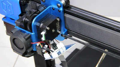
The ribbon cable leads to a tiny board, which serves as a distributor to the individual components of the extruder. 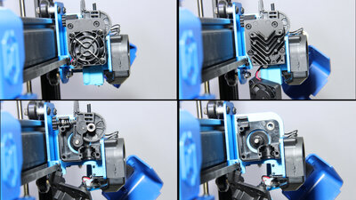
In case of a fault, the direct extruder can be dismantled quite easily with just one hexagon tool. The built-in stepper motor has a gear reduction of 3:1, with which the filament is powerfully pushed towards the nozzle. What looks like plastic gears is in fact solid metal. An advantage of the open gear design is that you can move the filament easily by hand. Print bed heating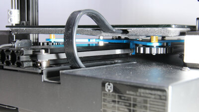
The maximum temperature of the print bed can be set to 130C° via the very responsive touchscreen. 40°C are reached after one minute, 60°C after 2 minutes, 90°C after 3 minutes and 100°C after only 4 minutes. After 5 minutes more than 120°C are reached, the 110°C specified by the manufacturer are easily within reach. The ambient temperature in my video studio at the time of the measurement was around 18°C. The high performance of the bed heating is achieved because it is operated with the mains voltage of 220V. As protection against the high voltage, the coated glass plate cannot be removed, but is glued to the aluminum plate of the bed heating. The mains voltage is supplied via a flexible, rubber-insulated cable on the back of the device - I don't see anything to complain about here. The bottom side of the print bed is also well insulated, both thermally and electrically. Levelling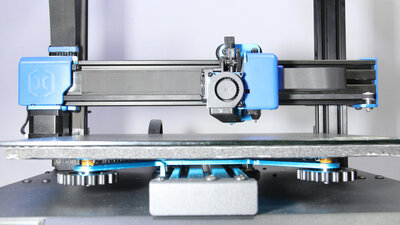
There is a sensor for automatic leveling of the print bed on the extruder. With the autolevel function, the print bed is measured at a grid of 25 points. Before the first start-up, the print bed should be adjusted following the classic method at the four corner points with a sheet of paper. The Z-offset of the sensor should also be determined using the paper method and don't forget to store the value afterwards. The autolevel function delivers good results, so that manual leveling should only be necessary rarely. With the four large handwheels, however, the height of the print bed can be comfortably fine-adjusted at any time - that's how I like it! Sample prints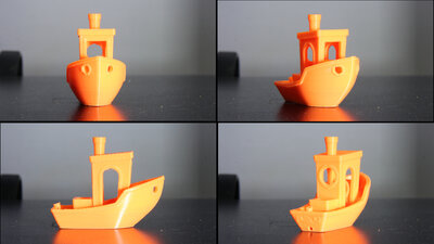
Benchy: Material: PLA Nozzle: 0.4mm Layer height: 0.2mm Dimensions: 60x31x48mm 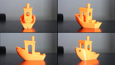
Benchy: Material: PLA Nozzle: 0.4mm Layer height: 0.2mm Dimensions: 60x31x48mm 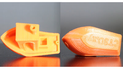
Benchy: Material: PLA Nozzle: 0.4mm Layer height: 0.2mm Dimensions: 60x31x48mm 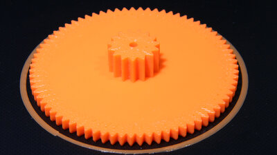
Gearwheel: Material: PLA Nozzle: 0.4mm Layer height: 0.4mm Dimensions: 78x78x15mm 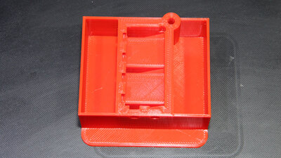
Piece for a CNC: Material: PLA Nozzle: 0.4mm Layer height: 0.2mm Dimensions: 110x100x35mm 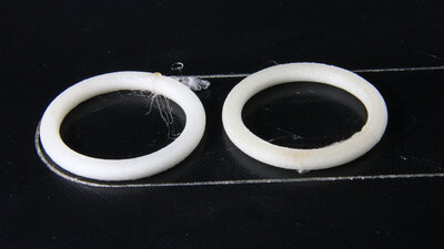
Rubber rings: Material: TPU Nozzle: 0.4mm Layer height: 0.2mm Dimensions: 45x45x4.5mm <<< Imprint ...to be continued. >>> News The Project Technology RoboSpatium Contribute Subject index Archives Download Responses Games Links Gadgets Contact Imprint |
|
|