|
|
|
|
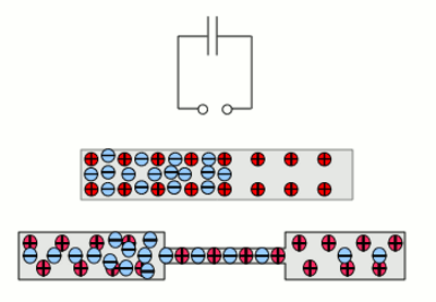
News The Project Technology RoboSpatium Contribute Subject index Download Responses Games Gadgets Contact <<< Self-inductance Energy of magnetic fields >>> Switching operationAn inductor isn't just inductor......a capacitor not just capacitor and a resistor not just a resistor. At the previous chapter we already saw, that the wire of an inductor always has a resistance. I don't know a super-conductive material, operating at temperatures of 20 °C and above. At the operating range of our electric vehicle, we always have to consider the presence of ohmic resistance at (mostly) copper wires. Capacitors are connected by wires to electric systems and those piping wiring is afflicted to resistance. Furthermore an electric circuit of a capacitor and a voltage source forms a loop of conducting material, thereby acts a little bit like an inductor. Film capacitors consist of two aluminum foils with an insulating film between. Those three layers are coiled up, which leads to additional inducting effects.
The electric circuit of a capacitor connected to a voltage source can be seen as an inductor with one winding. The charged particles of a metal-like conducting material can be displaced and therefore it acts like a capacitor. Even normal power lines are always capacitors, too. Charge displacement occurs "in front of" respectively "behind" a resistor, whereby they also act like capacitors. Switching-on and switching-offWe won't control our electric vehicle respectively it's electric motor by opening or closing a mechanical switch. At the chapters about semiconductors we will see, how electric switches work. By now I just like to touch the electric conditions "On" and "Off".Inside of an electric circuit, the condition "off" means the voltage between the connecting terminals is zero and electrons can pass unresisted. The condition "on" means that the voltage source (we examine DC-voltage) pumps electrons until the supplied voltage is reached. Furthermore we assume that the switching between the states "off" and "on" and vice versa occurs without a delay. 
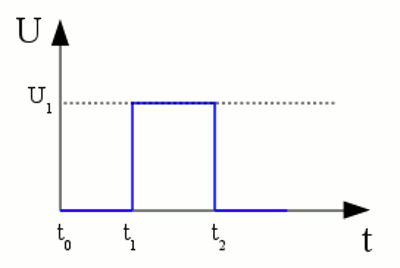
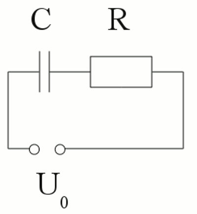
At t0 the voltage between the connecting terminals is 0V (=switched OFF). At t1 the voltage jumps to the supplied voltage U1 of the voltage source (=switching ON). At t2 the voltage jumps back to 0V (=switching OFF). Charging a capacitorAt the chapter about capacitors we saw that those electric devices store charges. The stored charge per volt is given by the capacitance. Those charge has to be moved into the capacitor and that doesn't happen without a delay. The time needed to charge a capacitor depends on the resistance of the wires of the electric circuit. This resistance can be symbolized by an ohmic resistor connected serially to the capacitor.
Serial circuit of a capacitor (C) and an ohmic resistor (R). Inside of the electric circuit, the sum of the voltages at each device equals the voltage of the input voltage: Before switching on, the input voltage and the voltage at the devices is zero: The correlation:
UC - Voltage at the capacitor, UR - voltage at the resistor, U0 - input voltage, I - total current, Q - charge, C - capacitance, R - resistor, t - time, e - Euler's number What do those formulas mean? 1.) At t = 0 the voltage at the capacitor is zero. For this reason the voltage drop at the resistance equals the input voltage U0. 2.) The current through capacitor and resistor is maximal at t = 0 and is given by U0 / R. 3.) The current increases permanently and tends to zero for t = ∞. Discharging a capacitorWhile charging the capacitor, energy has been stored inside of this device (see formula [3.5]). If the input voltage is set to zero, this energy is supplied to the electric circuit. The capacitor is discharged and functions like a voltage source. The current runs in the opposite direction of the charging process. Or:
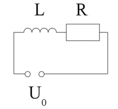
U0 - Voltage across the capacitor at t=0, I - total current, C - capacitance, R - resistance, t - time, e - Euler's number "Charging" an inductorAt the chapter self-inductance we saw that a voltage is generated inside of an inductor as soon as the current through the device is altered. The resistance of the inductor's wire plays a decisive role at this process.
Serial circuit of an inductor (L) and an ohmic resistor (R). Once more, the sum of the voltage drop at the single devices equals the input voltage: The correlation:
UL - Voltage at the inductor, UR - voltage at ohmic resistor, U0 - input voltage, I - total current, L - inductance, R - resistance, t - time, e - Euler's number While "charging" the inductor there is: 1.) At t=0 the voltage generated by the inductor equals the input voltage U0. The voltage drop at the resistor is zero. 2.) At t=0 the current through the circuit is zero. 3.) The current increases to U0 / R while t = ∞. The increase of current per time interval tends to zero. "Discharging" an inductorLike capacitors, inductors store energy, too. When switching off, the processes of self-inductance lead to a voltage keeping the current through the circuit alive. The direction of the current is the same as "pumped" by the voltage source. The voltage drop at the inductor alters it's sign and by now there is UL = -UR. The current is given by: For the voltage we get: IA - current at t=0, I - total current, L - inductance, R - resistance,UL - voltage at inductor, t - time, e - Euler's number <<< Self-inductance Energy of magnetic fields >>> News The Project Technology RoboSpatium Contribute Subject index Archives Download Responses Games Links Gadgets Contact Imprint |
|
|