|
|
|
|
News The Project Technology RoboSpatium Contribute Subject index Download Responses Games Gadgets Contact <<< Energy of magnetic fields DC motor (permanent magnets) >>> RLC circuitPendulumOscillation denotes the cyclic transformation between two forms of energy. Let's have a closer look at the processes of a mechanical system:
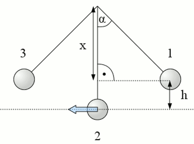
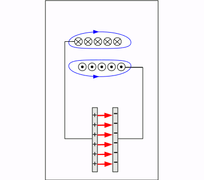
Pendulum: An iron sphere with the mass m is hanging on a thin cord of length l. Position (2) is the equilibrium position of the arrangement. Now the sphere is pulled back at an angle α. Thereby the sphere is lifted to the height h, leading to a potential energy of: The height h can be calculated with the help of the angle and the length of the cord: As soon as the sphere is released it starts falling down, accelerated by the earth's gravitational field. The cord forces the sphere to move on a circular path to the left. The potential energy is converted into kinetic energy while the sphere accelerates. Reaching point (2) the potential energy is completely transformed into kinetic energy: The kinetic energy causes that the sphere continues to move to the left. In doing so it is lifted again, moving on his circular path. The sphere is slowing down and potential energy is established. At position (3) it is brought to halt. Considering that there is no friction (air resistance, bending of the cord) the height h is equal to those at the start of the movement. The value of the angle equals those of the starting position, pointing to the opposite direction. The sphere starts moving to the right by now, converting the potential energy into kinetic energy once again until reaching point (2). Moving from point (2) to point (1) means transforming the kinetic energy to potential energy. Arriving at point (1) the sphere has run through a complete period and the process starts again. When considering friction, energy is permanently drawn from the system and converted into thermal energy. The elongation at the points (1) + (3) respectively the velocity at point (2) decreases until the pendulum stops at point (2). Energy transformation at LC oscillatorsLet's have a look at an electrical circuit consisting of an inductor and a capacitor. Nothing happens inside of such a circuit as long as there is no energy stored. Let's do this by charging the capacitor to the voltage U0. The voltage of the capacitor is applied to the inductor. Thereby the capacitor acts like a voltage source and gets discharged. Like told at the chapters about switching operations and self-inductance, a voltage is generated by the inductor working against the current through it. Thus the strength of the current is increasing strongly at the beginning and lesser at the end of the discharging process of the capacitor. The maximum current is reached as soon as the capacitor is completely discharged. The energy is transferred from the electrical field inside of the capacitor to the magnetic field of the inductor. Without an actuating voltage the current through the inductor decreases. According to Lenz's law a voltage is generated by the inductor which tends to keep the current flowing through it. Thereby the capacitor gets charged again, but with a different polarity. The induced voltage decreases to zero as soon as the magnetic field is completely dissipated. The energy is transferred to the capacitor once again. The discharging process of the capacitor starts again with a reverse direction of the current. Once again a magnetic field is generated by the inductor, whose field lines point to the opposite direction of the previous magnetic field. If the capacitor is completely discharged the inductor charges the capacitor anew. The polarity is the same as at the start of the experiment. One oscillation is complete and the process starts from the beginning. Without loss (ohmic resistance) the oscillation never stops.
Electrical circuit consisting of an inductor and a capacitor: Frequency of a LC oscillatorThe frequency of a lossless LC circuit is given by: Where is:f0 - frequency, L - inductance, C - capacitance Capacitors and inductors are never free of losses. The largest "handbrake" for the electric current is the ohmic resistance of the inductor's wire. It can be symbolized by an ohmic resistor being connected in series. 
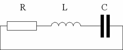
Electrical circuit consisting of an ohmic resistor (R), an inductor (L) and a capacitor (C). That's why an arrangement like this is called a RLC circuit. The resistor converts permanently electrical energy into thermal energy which is extracted from the system. Hence the maximal voltage respectively the maximal current through the devices decreases permanently until the whole energy is transformed into heat. For the resonance frequency we get: Where is: fr - resonance frequency, L - inductance, C - capacitance, R - resistance The resonance frequency is defined as the frequency at which the impedance (=resistance) is at it's minimum when the circuit is connected to an (mostly sinusoidal) AC-voltage. <<< Energy of magnetic fields DC motor (permanent magnets) >>> News The Project Technology RoboSpatium Contribute Subject index Archives Download Responses Games Links Gadgets Contact Imprint |
|
|