|
|
|
|
News The Project Technology RoboSpatium Contribute Subject index Download Responses Games Gadgets Contact Construction details of the model motorVideo about the electric motorConstructionWith a simple hommede motor I would like to demonstrate some base principles of electric motors. The rotor is made of a disc with permanent magnets while the stator consists of electromagnets.A fundamental feature is the arrangement of the permanent magnets on a disc, by what the electromagnets of the stator are formed straight (round bars), thus they are easy to build. Key dataThe model motor was built using a few tools as a saw, a drilling machine and some glue. The used materials are:
Those materials were not combined to a motor with perfect concentricity, but with the help of this construction we are able to check and demonstrate some base principles of electric motors. Each of the electromagnets consists of a round iron bar with a diameter of 8mm, a length of 37mm and approximately 300 windings of insulated copper wire (0.20mm2). When connecting one of the coils to a DC voltage of 5V, a current of approximately 800mA is running through the wire. 12 electromagnets form the stator of this stepper motor.  Even though the drawing implies the motor was incredibly accurate, it is in fact built using the "rule of thumb".
There is room for improvisation and your own ideas. 

Number of magnetic polesAs described above, the stator is made of 12 electromagnets. The simplest case would be to use a rotor disc with one magnet and to enable the electromagnets clockwise or counterclockwise. This control mode can be realized by using three or more electromagnets at the stator. Because of the fact that three electromagnets are sufficient to control the direction of the rotor, we can also use four magnets at the rotor disc and four groups per three inductors at the stator. By enabling one inductor per group, the torque of the motor will be quadrupled:
Cogging torqueThe core material of the electromagnets is iron. Ferro- or ferrimagnetic materials are used in electric motors to concentrate magnetic fields so that the resulting forces are boosted. Fores are acting between the core material and the permanent magnets of the rotor even if the electromagnets are disabled. The permanent magnets of the rotor and the round iron bars of the inductors are attracting each other resulting in a varrying torque depending on the angle of rotation. The model motor is composed of 12 electromagnets ( = 30° / inductor ) and four permanent magnets ( = 90° / magnet ) resulting in points of minimal respectively maximal attraction each 30°. When turning the rotor with the electromagnets disabled, you can feel the detent or "no-current" torque which is also called cogging torque.By adding more magnets to the rotor disc, the cogging torque can be reduced drastically. In case of this model motor we need four additional magnets. While first magnets are congruent to the inductors, each of the additional magnets has to be positioned between two inductors. Consequently the angle between two magnets is 45°: 
The action of forces at the first animation is highly idealized using a sinusoidal shape, which won't match the practical experience, because the shapes of permanent and electro magnets affect the resulting curve. Consequently the torque is not canceled out at the second drawing. RepulsionInstead of different polarities between electromagnets and permanent magnets, the rotor can also be moved by using a uniform polarity: Rotor movement with repellent forces.
The electromagnets of the stator are repelling the permanent magnets of the rotor disc if the north poles of the permanent magnets are facing the north pole of the electromagnets. At the drawing we are looking at the front of the electric motor. The south poles of the permanent magnets are pointing out of the screen, the north poles into the screen. The magnetic north poles of the electromagnets are pointing out of the screen, which is why they are repelling the magnets of the rotor disc (or the disc repells the stator). The repellent forces result is a torque. The electromagnets are enabled in such a way that they push the rotor. Control electronics model motor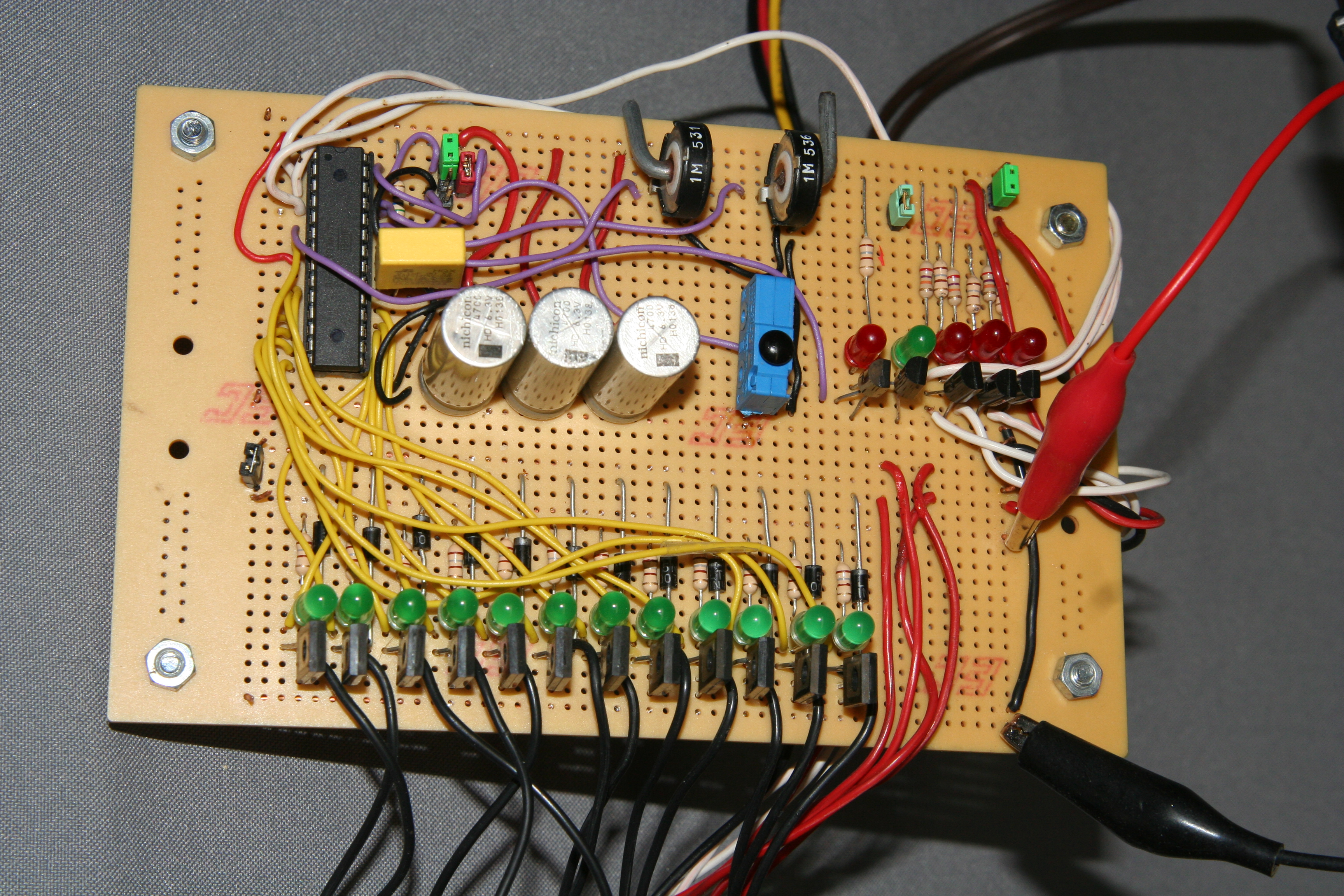
Construction12 transistors are used to switch the same number of electromagnets. Without using a H-bridge, the current through the inductors runs in one direction, thus the polarity of the electromagnets never changes. The control electronic is designed for a supply voltage of 5V DC. The power transistors can be connected to a voltage source up to 45V, but the copper wire of the electromagnets would melt in seconds if you would try to do so. For demonstration purposes, LEDs show the switching state of each transistor. If a LED is illuminated, the transistor below it is turned on and a current runs through the connected electromagnet. The LEDs can be disabled by a jumper.Two potentiometers (throttle and brake), one push button (forward/reverse gear) and three infrared photo sensors (rotor angle) are used as input devices. The state of the photo sensors is displayed by three red LEDs; one red and one green LED indicate the selected direction of rotation. Those LEDs can be disabled by a jumper, too. Three more jumpers can be used to activate different software modes of the microcontroller. The control and steering functionality is provided by an ATmega8A microcontroller. Parts list of control electronicsI used only parts I had in stock. Old computer mainboards or power supplies are a good source for electrolytic capacitors and jumpers.
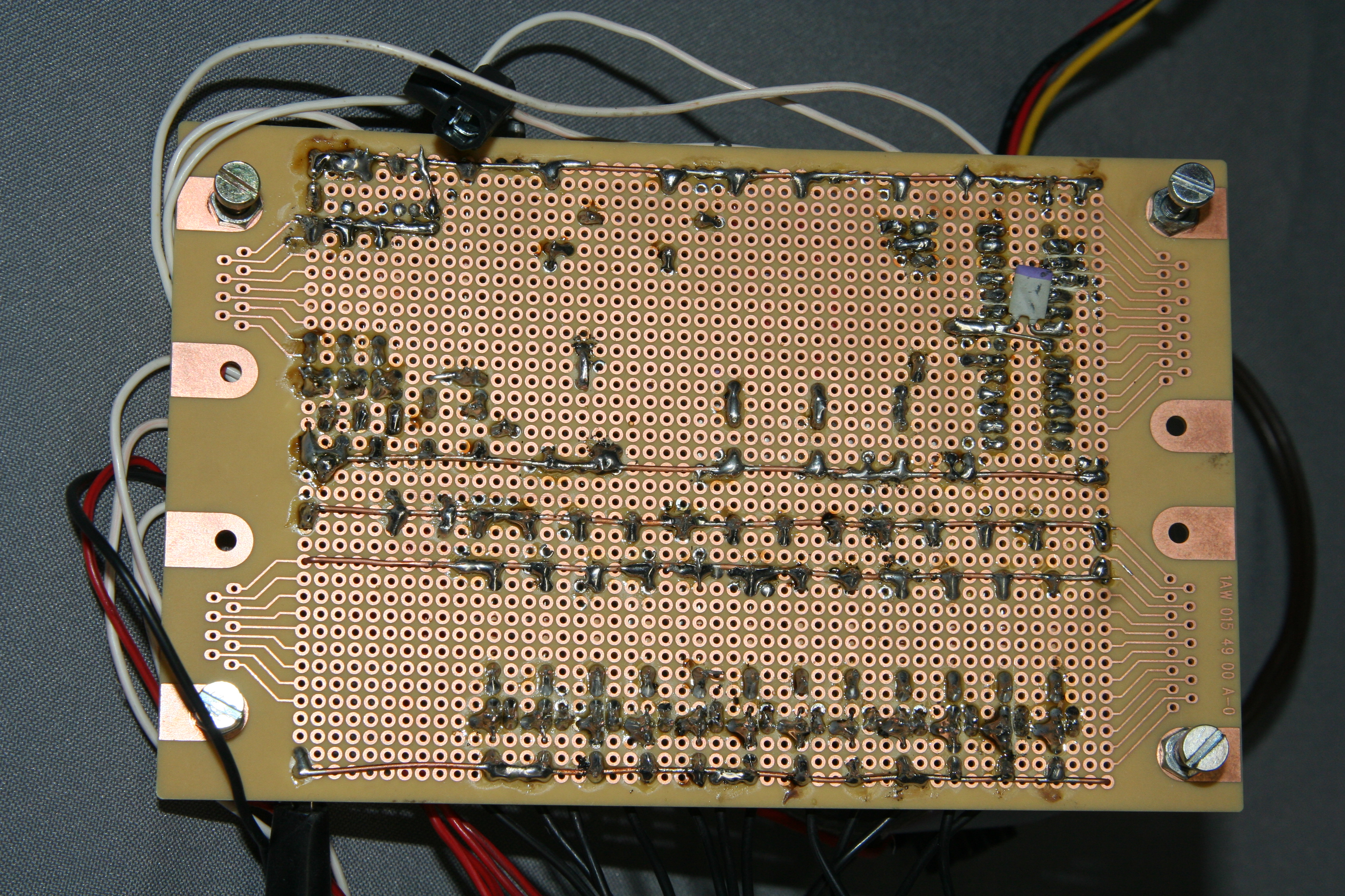
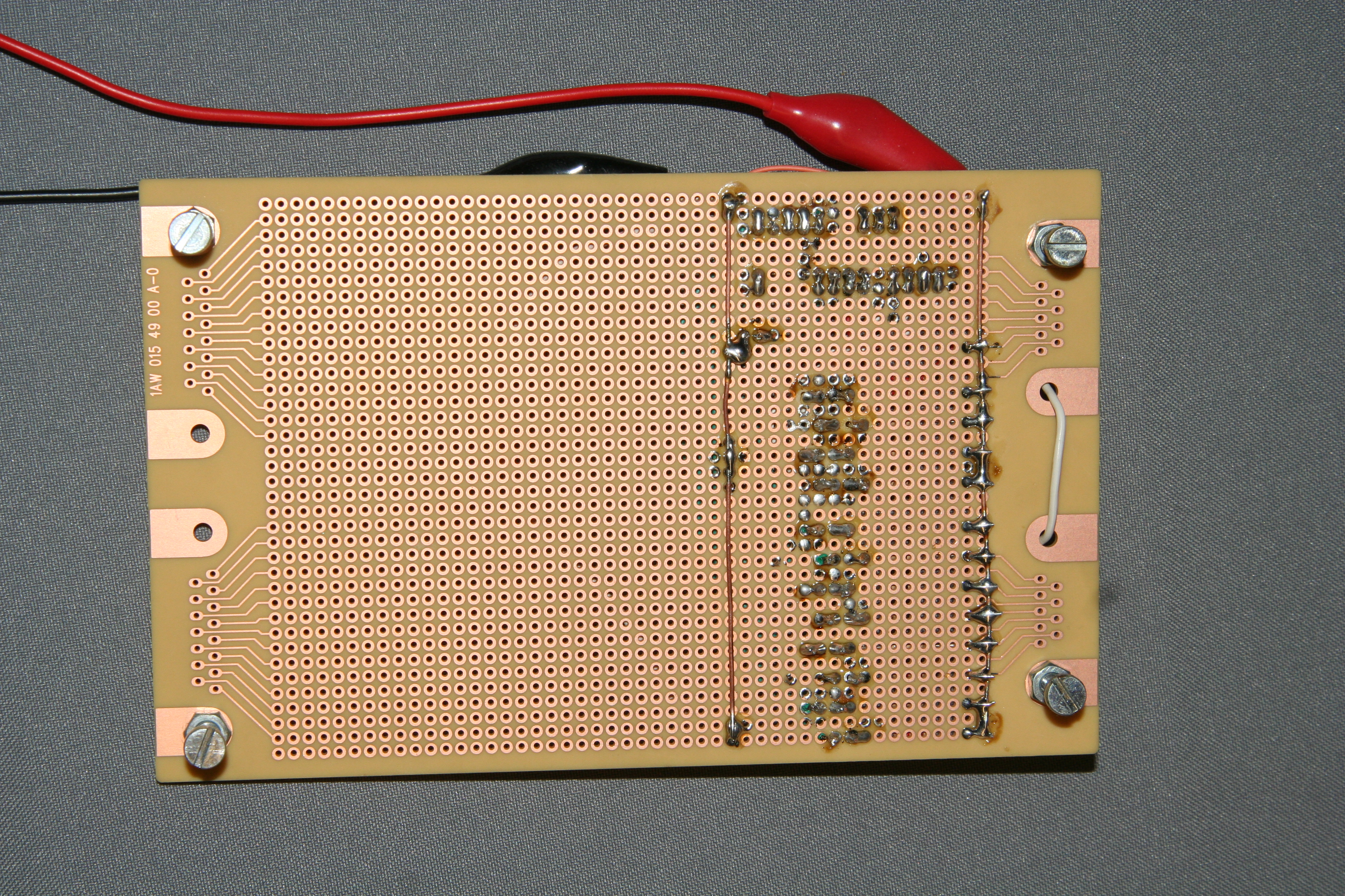
Wiring scheme control electronics Mainboard control electronics:
Click at the preview to see the full view of the drawing.  Photo sensors:
The wiring of the photo sensors is done without a circuit board. The devices are soldered straightforward. Click at the preview to see the full view of the drawing. Revolution counterSome experiments around this motor are done with a revolution counter, which is based on an ATmega8A, too. The number of revolutions is displayed either by a LED-bar or as a binary number and the counter is connected in parallel to one of the photo sensors.
Part list revolution counter
Wiring scheme revolution counter Mainboard revolution counter:
Click at the preview to see the full view of the drawing. Control software model motorMicroprocessorThe brain of the control electronics is an ATmega8A microcontroller with 3 counters, one 6 channel analog digital converter (ADC) and 23 programmable input output lines. This device controls the 12 electromagnets of the stator, the photo sensors of the rotor, the switches and the potentiometers of throttle and brake.System requirements of the softwareIf you are sitting in front of a 64bit computer, equipped with 4 gigabytes (4,000,000,000,000Bytes) of memory, 2.5GHz (2,500,000,000Hertz) double core processor and terabyte hard disc (1,000,000,000,000,000bytes) while reading these pages (because these are the minimal requirements for your operating system), you might be astonished about the resources of the microcontroller used here:The ATmega8A provides 8kilobytes (8,000bytes) self-programmable memory in cooperation with one kilobyte of RAM and 32 working registers. The speed can be set up to 8MHz (8,000,000Hz) and the calculation is done in a 8bit System. Sequence of enabling the electromagnetsTo get the switching sequence of the electromagnets, the used rotor disc (number of permanent magnets), selected rotational direction and polarity of the inductors has to be considered. With 12 electromagnets at the stator and 8 magnets at the rotor disc, the resulting sequence isThe current position of the rotor is detected by two photo sensors. Ignition timingDepending on the rotor speed and the direction of rotation it can be beneficial to shift the timing of enabling / disabling the electromagnets. Caused by the inductance of the electromagnets the current running through their windings is increasing slowly. The force acting between the electromagnets and the permanent magnets depends on the magnetic flux, thus on the current running through the windings. The higher the current, the higher the torque of the motor. At high rotational speeds, the turn on time of an inductor is short, by what the current running through the copper wire doesn't reach it's maximum. By altering the timing, the turn on time can be enlarged at higher rotational speed. If an inductor is enabled prior to it's normal timing, the time span is sufficient to reach the maximum current through the windings of the coil. Thereby a higher torque is generated at high rotational speeds. Compared to combustion engines, the "ignition timing" of the electric motor is adjusted. In doing so, the turn on time of electromagnets can overlap. Extension of the on-time:
At the top of this drawing, the current through the inductor is plotted against the on-time. Below the first plot, the attached voltage at the inductor is plotted as blue line and the red respectively green line give the voltages at the inductors to the left and right. By turning on the inductor ahead of time (right side), the maximum current through the inductor is increasing. The on-times of neighboring electromagnets overlap. Besides extending the on-time, t1 and t2 can be shifted similarly, whereby the current through the inductor doesn'T varry, but the point in time, where the maximum magnetic flux is reached shifts. Ignition timing of the software can be activated by two jumpers connected to pin 26 and pin 27 of the microcontroller. Forward / reverse gearThe selection of the rotation direction of our experimental motor is done by a push switch. It has to be guaranteed that the rotation direction can't be altered while the motor is rotates.Another safety function concerning the reverse switch is the fact that it has to be pushed for more than one second to change the rotational direction. Throttle / BrakeWhat happens, if throttle and brake are actuated simultaneously? One of the pedals must have a higher priority than the other one.The execution of the brake functionality is skipped, if the throttle pedal is actuated (throttle is prioritized). Speed controlDriving with constant speed is very comfortable and first of all very energy-efficient. It is done by an automatic speed control, which must be disabled while throttle or brake are actuated!The preselected speed is stored in the register value SetSpeed, the currently detected speed uses the register value ActualSpeed. If throttle or brake pedal are actuated, the value of ActualSpeed is copied into the value SetSpeed. By braking or accelerating, the preselected speed is readjusted. The speed control is enabled or not by the jumper connected to pin 26. If the jumper is set (=switch closed), the speed control is active. The state of the jumper is stored in the register value ControlBits (bit 3). The execution of the speed control is skipped while throttle or brake pedal are actuated. Remarks on the sensor discThe sensor disc is designed to use two photo sensors. Four different steps can be encoded at that way:
Ensure that between two steps of the sensor disc, just one of the photo sensors changes it's state! If a photo sensor is at an edge of the sensor disc, it will jump multiple times between ON and OFF. If just one of the photo sensors changes it's state, the position of the sensor disc can still be detected accurately (either at the left or the right of the edge). If both photo sensors would change their state simultaneously, the position of the disc could not be detected reliably:  At the upper drawing, the upper photo sensor jumpes between 0 and 1. For this reason the calculated position of the rotor jumps between the values 3 and 4, which matches the real position (it is between step 3 and 4). At the middle drawing both photo sensors oscillate between 0 and 1, whereby the calculated position can be 1, 2, 3 or 4. The position of the sensor disc can't be calculated reliably by the software. The disc should be designed as shown at the lower drawing.

 You can get the source code of at the column downloads.
Performance data of the experimental motorMeasurement setupTwo digital multimeter were used to record the input voltage and the current running through the stator. The resulting electric input power can be calculated using formula [3.8]. The revolution speed was detected by using the self-made revolution counter. The motor was slowed down with a cord being wrapped around the rotor axis. The force acting on the cord was measured indirectly by a kitchen scale. The displayed weight, multiplied by the gravitational acceleration (9.81m/s2) results in the force acting on the rotor axis. With the help of a sliding caliper, the diameter of the rotor axis was determined to be 25mm. To calculate the mechanical output power, revolution speed, force and diameter are needed. With the definitions of torque ([2.14]), mechanical work ([2.10]) and mechanical power ([2.13b]) we get:POut = m * g * n * d * π Where is:POut - mechanical output power, m - mass in kilogram, g - gravitational acceleration, n - revolutions per second, d - diameter of the rotor in meter, π - 3.14 When input and output power are known, the efficiency is given by formula [4.3]:
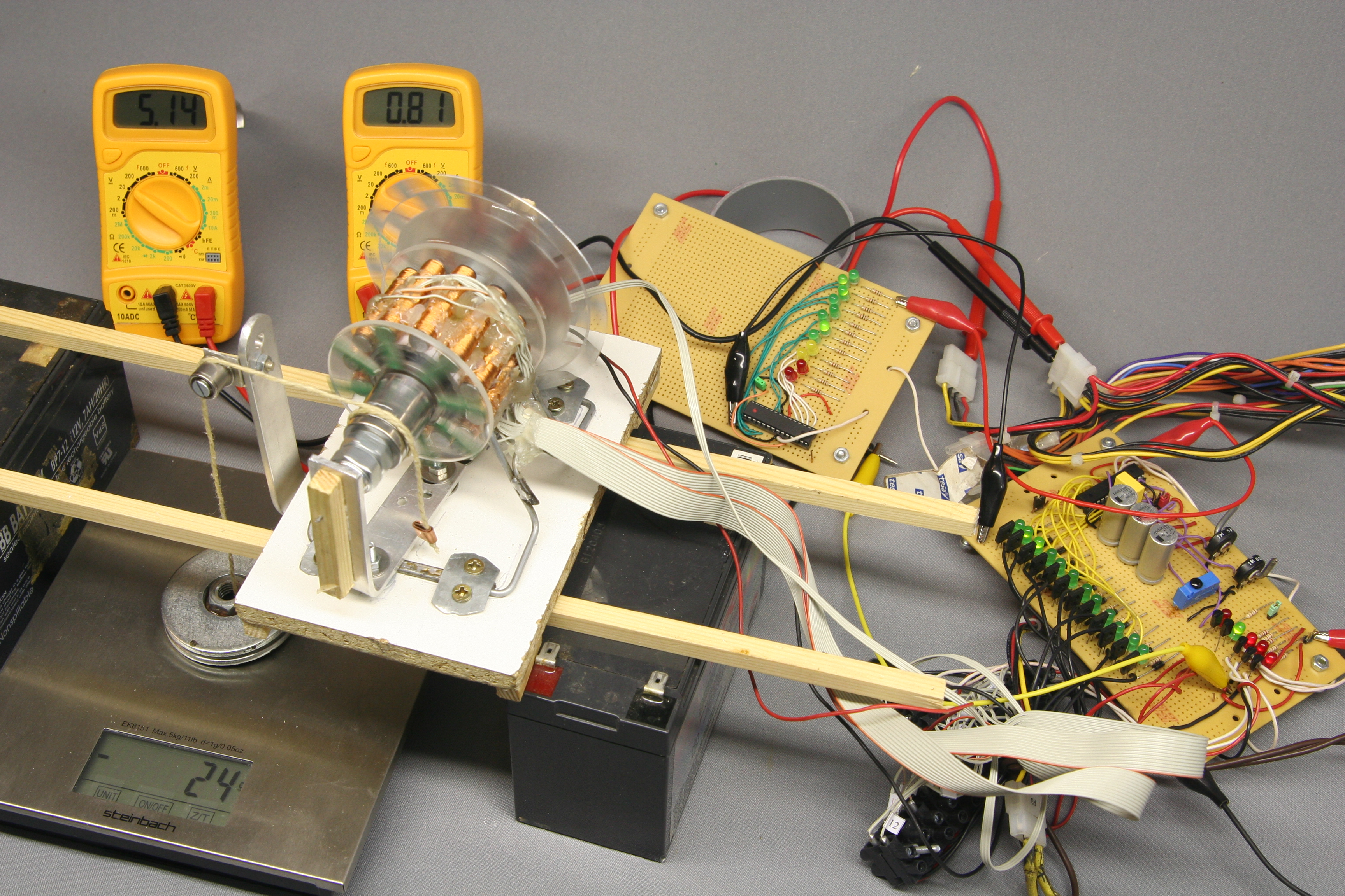 Used equipment:
Two digital multimeter, a kitchen scales, a sliding caliper (not at the picture) and the self-made revolution counter. Measurement valuesAt the table below you can find the measurement values and the calculated efficiency.
That couldn't be worse! Where has all the input power gone?Well, this experimental motor was built on the fly. The dimensions were given by the available materials and the sparse usage of tools lead to a very poor mechanical accuracy of the motor. If you have watched the video, you will have noticed that the motor is wavering considerably. Let's have a closer look at the weak points.Core materialThe core material of the electromagnets is made of a massive piece of ordinary iron. As mentioned in the chapter about core loss, the usage of a stack of soft iron would be much better to minimize the eddy currents. The used iron is not magnetically soft, which increases the core loss, too.Coil windingWhile connecting one of the electromagnets to a DC voltage of 5V, a current of approximately 0.9A is running through the copper wire. So the ohmic resistance is about 5.56Ω and a power of 4.5W is converted into heat while this current is running. When looking at the recorded values, you can see that the current running through the stator is very close to its maximum:
Air gap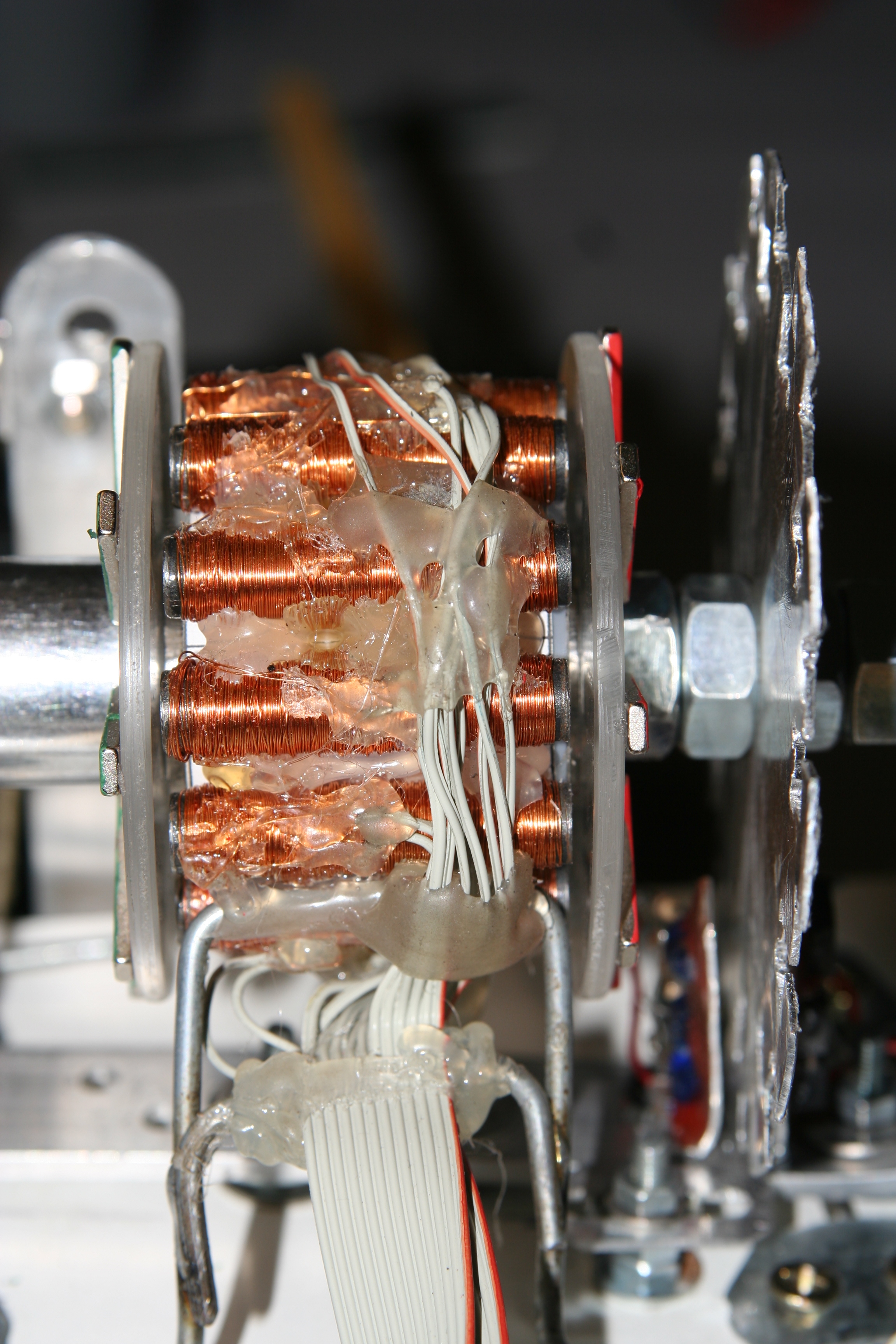 The poor manufacturing quality of the experimental motor leads to a huge air gap between stator and rotor discs, Thus a large portion of energy is lost because of the poor coupling between the magnetic fields of the electromagnets and the permanent magnets!
Sensor discThe sampling rate of the sensor disc is very rough. The smaller the distance between two states of the photo sensors becomes, the more precise the timing of the electromagnets can be adjusted. As you can see at the results of the measurements, the timing is essential for a good efficiency.TransistorWhile one of the transistors is turned on, a voltage of 0.25V can be detected and a current of 0.9A is running through the device. Hence the resistance of the enabled transistor is 0.28Ω and 0.2W of electrical power are roasted inside of it. Transistors with a lower ON-resistance are helpful to increase the efficiency.News The Project Technology RoboSpatium Contribute Subject index Archives Download Responses Games Links Gadgets Contact Imprint |
||||||||||||||||||||||||||||||||||||||||||||||||||||||||||||||||||||||||||||||||||||||||||||||||||||||||||||||||||||||||||||||||||||||||||||||||||||||||||||||||||||||||||||||||||||||||||||||||||||||||||||||||||||||||||||||||||||||||||||||||||||||||||||||||||||||||||||||||||||||||||||||||||||||||||||||||||||||||||||||||||||||||||||||||||||||||||||||||||||||||||||||||||||||||||||||||||||||||||||||||||||||||||||
|
|