|
|
|
|
News The Project Technology RoboSpatium Contribute Subject index Download Responses Games Gadgets Contact <<< EDM: Wagners Hammer (2) EDM: Active Hammer (1) >>> "Wagners Hammer", Part 3: DC motorsThe video about engraving with Wagners Hammer, Part 2Commercial lifting magnet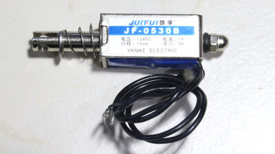
In the previous two previous chapters I showed how to use a self-made lifting magnet to engrave metal. To see what commercial lifting magnets are good for, I bought a rather cheap one. Disadvantage number 1: The anchor is anything but free of backlash. Disadvantage number 2: The specified current of 1A at 12V turns out to be only 770mA with a falling tendency during operation as the coil wire heats up. Nevertheless, the lifting magnet initially works quite well as a Wagner hammer. After a few seconds, however, no more sparks can be seen. In the previous video I had already shown that the current should be well above 1A in order to produce consistent engravings. DC motor as Wagner Hammer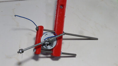
What is needed is a motor that draws a stall current of significantly more than one amp at the intended direct voltage, without ending up in magic blue smoke. The first motor I chose, draws a current of 300mA at 3.3V when the shaft is blocked, 650mA at 5V and a current of 2A at 12V. Here, too, you can see that the displayed value decreases as the measurement progresses because the enameled copper wire inside the motor heats up. For a first, simple conversion of the motor to a Wagner hammer I have glued a 3mm threaded rod to the shaft at which the electrode wire can be clamped. A wire leads from this threaded rod to one terminal on the motor - the second terminal is connected to ground of the power supply. As is usual with a Wagner hammer, the electrical circuit is closed via the workpiece as soon as the electrode touches the material surface. The motor must be connected so that the electrode is then raised. At the other end of the threaded rod, a piece of steel wire ensures that the electrode is lowered to the mechanical stop when no current flows through the motor windings. By attaching the electrode to a rotating lever, it inevitably moves in a horizontal direction along the surface whenever it is raised or lowered. The motor is operated in a mode for which it was never designed: The motor is constantly starting, but only rotates for a fraction of a degree and is then moved back by the spring. The rotor never actually rotates. A too high current flows through the windings and cooling by a rotating rotor is completely missing. After the 5-minute engraving, the motor housing is not excessively hot and no smoke rises from the inside of the motor. 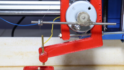
The next electric motor draws a stall current of 700mA at 3.3V, 1.2A at 5V and 2.8A at 12V. To prevent sideways movement when lowering the Z axis, I use a brass tube to guide the wire. This is squeezed at the bottom end so that the 0.2mm wire can move only in longitudinal direction without much friction. As before, a piece of spring wire causes the hammer to be pushed down to the mechanical stop when no current is flowing through the motor windings. With this motor I noticed how important the adjusted spring tension is and that the system must move with as little friction and as little backlash as possible. During the first attempts, the motor vibrated strongly and was therefore unusable for engraving. The downforce of the electrode varies with the height of the Z axis of the CNC, which can be seen and heard. If everything is set correctly, this motor also works as a Wagner hammer at 12V. 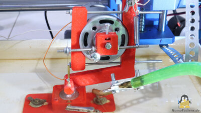
The third engine in my test series is also the most powerful. This draws a current of 2.7A at 3.3V, 7.2A at 5V and a scary 15A at 12V. With 5V I have achieved the best engravings so far. At 3.3V the engraving is rather weak, at 12V too much power flows through the system, which leads to less good results. With a power supply that can deliver a current of 20A at 12V and with a thicker electrode than the 0.2mm tungsten wire, this motor can be used when deep but not so fine engravings are required. Like the previous two, this motor does not come from a cannibalized printer. I received this from RS Components. HomoFaciens Coin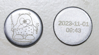
The engraving seen here was done with the most powerful motor of my test series at 5V. The "coin" has a diameter of 20mm, the graphic is 15x16mm small. The time stamp of production is engraved on the back with a digit height of 2.2mm. Engraving was done using 0.2mm tungsten wire as an electrode. If you would like to purchase such a "HomoFaciens Coin" to get an own impression of how good the engraving is: You can support me financially in my experiments and receive a "coin" like this as a thank you for donations of €15 or more (don't forget to mail me your postal address if you want a coin). 3D filesI have designed the files with OpenSCAD. The scad file as well as all parts as STL files are available as download package. I used PET-G to print the parts.<<< EDM: Wagners Hammer (2) EDM: Active Hammer (1) >>> News The Project Technology RoboSpatium Contribute Subject index Archives Download Responses Games Links Gadgets Contact Imprint |
|
|