|
|
|
|
News The Project Technology RoboSpatium Contribute Subject index Download Responses Games Gadgets Contact <<< EDM: Wagners Hammer (3) EDM: Active Hammer (2) >>> EDM: 'Active Hammer', Part 1The video about engraving with an 'Active Hammer', Part 1'Active Hammer', Version 1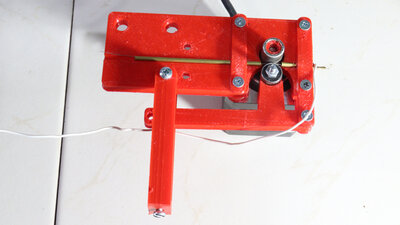
In the previous theree chapters I demonstrated what can be done with a "Wagner Hammer" The next stage of experimentation makes use of a provcess I call "active hammering" with a stepper motor controlled by a microcontroller. The stepper motor only moves the electrode wire back and forth - the moving mass is therefore as small as can be. On the stepper motor there is a piece of steel tube with an outer diameter of 10mm, which I roughened with a Dremel so that there is enough friction to move the wire. A ball bearing with an outer diameter of also 10mm serves as the counter part. This ball bearing is pressed onto the stepper motor roller via a lever and a spring. The wire is guided through brass tubes with an outer diameter of 2mm. Since I use electrode wire with a thickness of only 0.2mm, I crimped the bottom tube. When crimping, a steel wire with a thickness of 0.5mm prevents the inner diameter of the brass tube from becoming too small. Electronics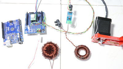
The circuit runs via the lower brass tube and therefore the electrode wire that rubs against the inner wall. There is an inductor in the circuit for mainly two reasons: If the circuit is closed via the workpiece, an induction voltage builds up in the coil, which counteracts the external voltage - the current does not increase abruptly, but rather slowly. On the other hand, if the electrode wire is lifted and the conductive connection to the workpiece is interrupted, the induction voltage now causes the resulting spark to be maintained for a little longer. The stepper motor is controlled via an ATmega328 microcontroller with an A4988 stepper motor driver. So that the microcontroller can detect whether the wire is touching the workpiece or not, there is a sensor in the circuit - this can measure currents of up to 30A. The logic of the microcontroller software is quite simple: If the sensor reports that no current is flowing, the wire is moved downwards. However, if a current flows, the wire is moved upwards. Known issues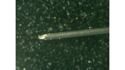
Here you can see a new piece of 0.2mm tungsten wire under the microscope... 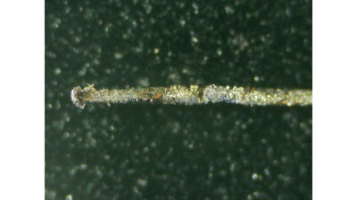
...and here the same material after the 12V torture. In the next iteration I have to ensure that there is a well-defined contact between the feed mechanism and the electrode wire. In the brass tube, sparks jump uncontrollably onto the wire and cause undesirable erosion of the electrode even before it touches the workpiece. 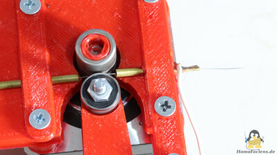
If you look closely at the roller for the wire feed on the shaft of the stepper motor, you will notice that it appears to push the wire down faster than it could be the case due to the electrode wear. The reason is that the wire is hammered onto the workpiece so hard that visible slippage occurs on the transport roller - this is also not good for the electrode wire. 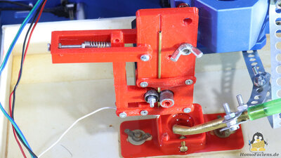
Furthermore, the two steel rollers of the feed mechanism flatten the wire and these shear forces cause it to partially split. A more gentle mechanism for feeding the wire is needed. HomoFaciens Coin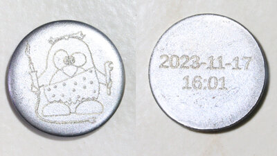
The engraving seen here was done with 5V and the coil with the higher inductance. The "coin" has a diameter of 20mm, the graphic is 15x16mm small. The time stamp of production is engraved on the back with a digit height of 2.2mm. Engraving was done using 0.2mm tungsten wire as an electrode. If you would like to purchase such a "HomoFaciens Coin" to get an own impression of how good the engraving is: You can support me financially in my experiments and receive a "coin" like this as a thank you for donations of €15 or more (don't forget to mail me your postal address if you want a coin). 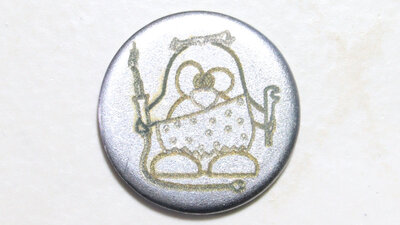
The engraving of the "HomoFaciens Coin" shown here took almost an hour with just 0.1mm/s and is therefore not going into series production - if you are interested, make me an offer. 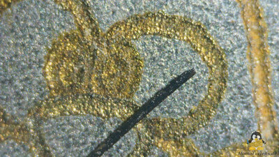
The lines can be seen here under the microscope compared to a piece of 0.2mm tungsten wire used as electrode. After a few hours a golden brown layer has formed in the lines. I can't say exactly what it consists of. Deposits of brass or the formation of an "alloy" with components of the tungsten wire would be possible. Or it is simply the good old rust. DownloadsI have designed the files with OpenSCAD. The scad file as well as all parts as STL files and the Arduino sketch are available as download package. I used PET-G to print the parts.<<< EDM: Wagners Hammer (3) EDM: Active Hammer (2) >>> News The Project Technology RoboSpatium Contribute Subject index Archives Download Responses Games Links Gadgets Contact Imprint |
|
|