|
|
|
|
News The Project Technology RoboSpatium Contribute Subject index Download Responses Games Gadgets Contact <<< EDM: Introduction EDM: Flushing >>> EDM: Microscopic viewThe video about the EDM microscope view
You can buy the Andonstar AS246 microscope on: How the photos were taken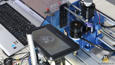
The fact that the CNC, on which my Electrical Discharge Machine is based, is controlled by open source software has proven to be advantageous for the project. A few extra lines of code now cause the table with the razor blade to move forward under the microscope after each spark,to record the result and then to move back under the drill. The remote control for the microscope is triggered by a movement along the X-axis of the CNC machine via a glued on pen. 15 seconds are needed for each photo. Drilling through a 0.1mm razor blade
The first image shows the surface of the razor blade. The metal is covered with grooves that run parallel to the longitudinal axis of the blade. The parallel grooves on the surface of the razor blade hardly move from image to image under the microscope. The table of the CNC machine is obviously moved back and forth very precisely between the drill and the microscope, which means that incorrect positioning as the cause of the different lightning strikes can be ruled out. 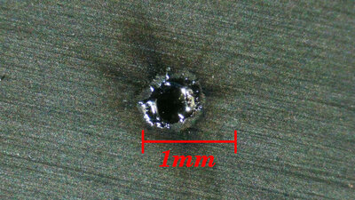
The very first spark leaves a clearly visible crater on the surface of the razor blade. The diameter is about 0.7mm. It can be seen that the metal has melted and then solidified again. The irregularly shaped edge of the crater is not sharp but rounded by the ejected, molten metal, which also goes well above the surface of the razor blade. 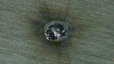
The second spark does not deepen the crater any further - it can be seen that molten metal has flowen back into the first crater. You can also see that the second spark did not hit the surface in the exact same spot - the crater has been expanded to the top right of the photo. This is a basic principle of spark erosion: As with a thunderstorm in the earth's atmosphere, the spark from this artificial mini-thunderstorm only very rarely strikes the exact same spot again. I will go into the "why" in more detail in the chapters on plasma formation. 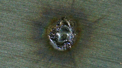
With spark number eight, the 0.1mm thick razor blade is "shot through". This opening does not get bigger with the following "shots". The sparks strike in a distance from the edge of the hole. 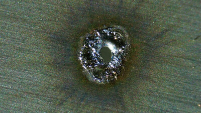
"Shot" number 13 leads to a significant increase in the diameter of the hole. 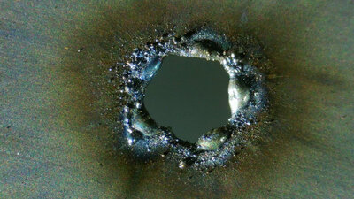
The opening is enlarged spark by spark, although no circular hole is formed. The edge of the opening is very irregularly shaped - places with thick material alternate with thinner areas. The molten metal thrown out by the sparks piles around the resulting hole. There is a clear discoloration of the metal to shades of blue around the hole and on the resolidified material, which is due to excessive heat exposure. Furthermore, tiny particles made of metal that is quickly oxidized in the environmental air accumulate around the hole. In addition to physical effects such as the melting or evaporation of material, a large number of chemical processes also take place in the oxygen-rich ambient air. You can see that the sparks melt different amounts of metal. Sometimes a lot of metal is removed, then again only very little metal disappears and also in more than one just place. It obviously happens that more than a single spark is formed and the energy is thus transmitted in a less concentrated way. I therefore prefer to speak of one shot per frame rather than one spark per frame. 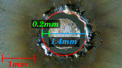
After 99 shots, the opening is so wide that the 1mm drill dips in without further sparks jumping - the drilling process is complete. In principle, the experimental setup works and a hole is drilled into the hardened steel of a razor blade. Under the microscope, however, this hole does not look very nice. If the shaft of the drill is added to the image, it can be seen that the hole has become significantly larger than the 1mm drill specifies. The diameter is about 1.4mm and is anything but circular. One reason for the excessively large diameter is the imperfect runout of the milling spindle and another one the inaccuracy in the positioning of the milling table. But of course the gap, which can be jumped over by the sparks with the applied voltage of 30V, is decisive. In addition, metal particles ripped out can form a conductive bridge for a short time and thus increase the spark gap even further. If we assume the runout of the milling spindle and the positioning to be perfect, this gap is around 0.2mm. Drilling through a 0.5mm blade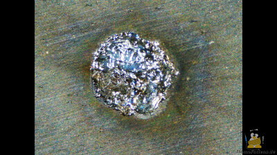
This hole is drilled into a knife blade, also made of hardened steel, with a material thickness of about 0.5mm - this blade is therefore 5 times thicker. 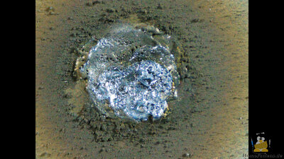
Material thrown out quickly accumulates around the drilling site. 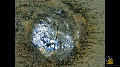
It can be seen that during the drilling process a crack forms in the center of the hole. Due to the constant melting and cooling, huge stress is applied to the material, which causes the steel to crack. 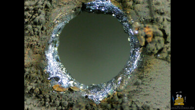
Significantly more than just 500 shots are needed to pierce the blade, which would be five times the razor blade with a fifth of the material thickness, which is partly due to the fact that the thicker material can dissipate heat more efficiently. Therefore, less metal is melted per shot. When the hole gets deeper, the metal particles can no longer be thrown away as effectively - a large part of the material gets stuck in the drill hole and solidifies there again. After 7617 shots, the drill process is complete. 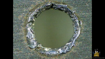
The hole after cleaning. The drill bit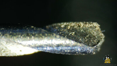
Let's take a close look at the 1mm drill, because this is also made of steel. The initial state can be seen here. 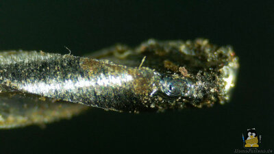
After drilling a few holes in the razor blade, you can also see molten metal at the tip of the drill - the sparks obviously work in both directions. If the molten metal of the drill combines with the liquid metal of the razor blade, the two parts can weld together. The milling spindle is switched on so that the drill moves quickly enough to prevent that welding from happening. 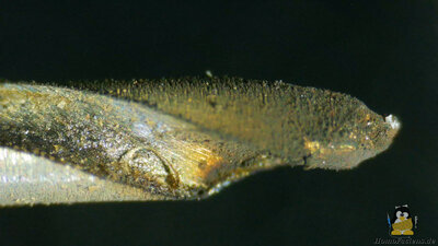
After drilling through the 0.5mm blade. <<< EDM: Introduction EDM: Flushing >>> News The Project Technology RoboSpatium Contribute Subject index Archives Download Responses Games Links Gadgets Contact Imprint |
|
|