|
|
|
|
News The Project Technology RoboSpatium Contribute Subject index Download Responses Games Gadgets Contact <<< EDM: Flushing EDM: Electronics (1) >>> EDM: Plasma propertiesThe video about the properties of plasma in the process of EDM
You can buy the Andonstar AS246 microscope on: Sparks under a microscope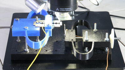
To opserve sparks with my microscope, I added some more parts in order to be able to move the drill and razor blade towards each other with reasonable precision. The two mechanisms work with a preload that can be reduced via a 3mm screw to move the drill forward. The tube with a glass bottom that I glued on for the underwater microscopy acts here as a protection for the lens from metal particles flying around. The 3D files are available as download package. 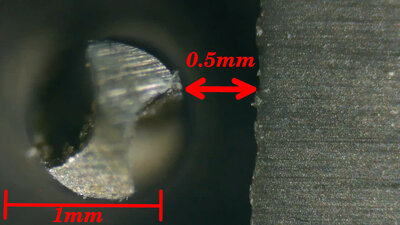
The drill bit has a diameter of one millimeter which gives us the scale of the magnification. The 0.1mm thick razor blade, on the right side, is not aligned with the cutting edge, but with a blunt edge pointing towards the drill. The drill bit is aligned so that a cutting edge points towards the razor blade - as we will see later, this is ideal for bridging a gap. The distance in the initial state is about 0.5mm and no sparks can be seen. 
At 0.2mm nothing happens. Even at 0.1mm, no spark can be seen. 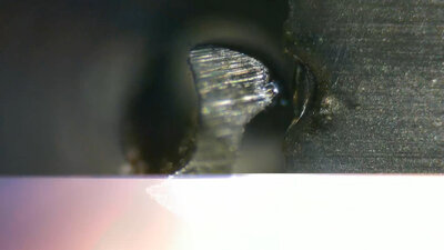
Not until the "touchdown" does the expected flash appear. My experimental setup is therefore not suitable for capturing the gap at which the spark jumps over. Didn't I talk about a "touchdown", of drill and razor blade? Well, let's say it this way: If you could look at the two objects at the atomic level, there would still be a gap to be seen. In a comment on an earlier video of this series, someone used the term "spark planer" in relation to my machine, and that's a good description. The time resolution of the recording was also rather disappointing: The flash can only be seen in a quarter of a single frame - the frame rate of the microscope camera is simply far too low to capture the spark. However, there remains an upper limit that can be estimated for the process, namely the frame rate of the camera and with that we get 17 milliseconds, if the metadata of the video file should be true. 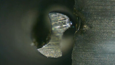
That spark not only melted the metal of the razor blade, but also that of the drill bit - in the previous videos I had already mentioned that sparks works in both directions. The resulting gap between both objects after the spark occurred is about 0.06mm. The edge of the razor blade has been eroded over a length of about 0.5mm. 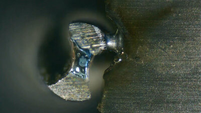
Not all sparks are the same and material is not removed from the razor blade with every "shot". The drill bit and razor blade often weld together. The question as to why the drill bit on my simple EDM machine has to rotate should be answered satisfactorily. Experiments with a high voltage generator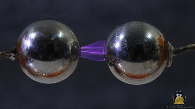
When the two 20mm steel balls, connected to the terminals of this generator, approach, sparks appear at a distance of about 6mm. Multiple channels of purple glowing plasma form between the two poles. There is no single, stable plasma channel formed between the closest points of the two steel spheres, instead the sparks constantly move around on the surface. 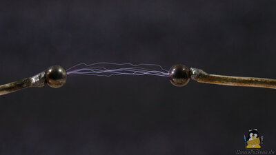
Let's change the diameter of the steel balls to just 5mm: Now sparks jump over at a distance of 24mm. If the distance is further reduced, the sparks jump over at a faster rate. 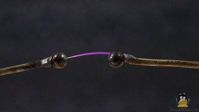
With a distance of only 12mm, a stable plasma channel forms between the balls, which continues to move around the surfaces. 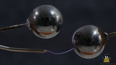
After replacing the balls with sharpened wires, even a gap of 35mm can be bridged. Conversely, this means that the spark is more likely to jump to an area with a sharp edge than to an area with a larger radius. Here, the plasma favors to form between the right steel ball and the left wire tip, although the gap to the second steel ball is only about half as large. 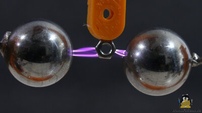
As another experiment, I bring a metal particle in the form of an M3 nut between the two 20mm steel ball electrodes. Now sparks jump over at a distance of more than 10mm without the nut touching one of the two electrodes - the simulated metal particle expands the maximum possible spark gap by the diameter of the nut. Impurities therefore play a considerable role in the processes of spark erosion. Resistance estimation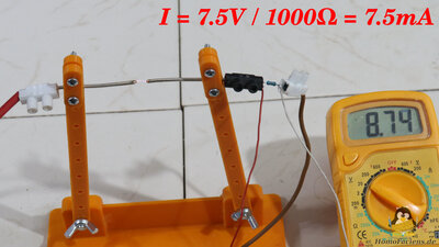
To measure the current I put a 10 Ohm resistor in the circuit. With a voltage drop of 0.07V, this results in a current of 7mA at an electrode spacing of 5mm. If we bring the wire tips closer together, the current increases. If the distance is brought back to 5mm and the current sensor is replaced by a 20 Ohm resistor, 0.13V can be read, which is also equivalent to about 7mA. With a 100 ohm resistor we get about the same current, which doesn't really change even with a 1000 ohm resistor. Consequently, assuming that the high-voltage generator delivers a constant output voltage, the resistance of the plasma must be significantly higher. 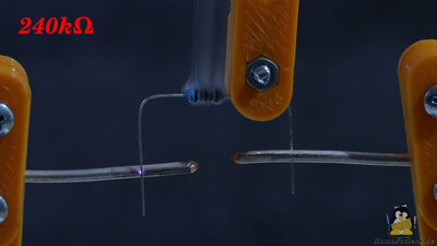
So let's narrow the resistance value from the top range by putting a 1 megaohm resistor in parallel to the plasma. No change can be seen - consequently the resistance of the plasma must be significantly lower. Even with a 500 kilohm resistor in parallel, the plasma arc is maintained. However, the 240 kiloohm resistor interrupts the plasma and emits magical blue smoke. The resistance of the 5mm long plasma arc must therefore be in the range of 200 kilohms. Yeeees, I know, the two experiments only allow a very rough estimate of the actual resistance, since the voltage source really does not deliver DC voltage free of any impedance, but I don't want to discuss that at this point. Let's note that the resistance of the gap between the electrodes decreases significantly with the appearance of a spark, but it does not become zero. Draht erodieren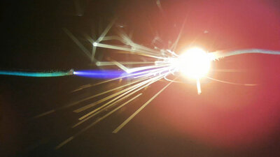
As the next experiment, let's attach two thin wires to the terminals of the high-voltage generator and turn on the power: Now it can actually be observed that the wire tip to the right, which is connected to ground, begins to glow and melts. At a distance of about 10mm the gap remains constant, a ball of molten and re-solidified metal has formed at the tip of the right wire. In a previous experiment we saw that the current flow decreases as the distance traversed by the plasma increases. The longer the distance, the lower the electrical power that drops across the spark gap, because the power drop is proportionally to the current, considering the voltage to be constant. The energy of the plasma is also distributed over a larger volume, which means that more energy is released into the surrounding air and therefore less into the wire ends. Furthermore, the energy absorbed by the thick drop of metal spreads over a larger volume, which also prevents more metal from melting. <<< EDM: Flushing EDM: Electronics (1) >>> News The Project Technology RoboSpatium Contribute Subject index Archives Download Responses Games Links Gadgets Contact Imprint |
|
|