|
|
|
|
News The Project Technology RoboSpatium Contribute Subject index Download Responses Games Gadgets Contact <<< Servos Encoder disc (2) >>> Encoder discThe video about encoder discsTransmissive photoelectric sensor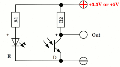
Photoelectric sensors are composed of a photo transistor and an LED. As long as the photo transistor is not exposed to light, the resistance of it's emitter-collector at least severan Kiloohm. Whenever light hits the device, the resistance drops to just some ohms. With a voltage divider composed of the photo transistor and a constant resistor of some Kiloohm the varying resistance of the emitter-collector line is turned into a varying voltage. The input voltage is usually 3.3V (e.g. for a Raspberry Pi) or 5V (e.g. Arduino). To turn the LED "on", the cathode of the infrared diode which is marked with an "E", has to be connected to the negative terminal of the voltage source, the anode marked with a "+" has to be connected to plus of the DC voltage through a series resistor (R1) used to limit the current. The resistance value depends on the input voltage and the forward current of the LED. Have a look at the datasheet of your sensor unit to find the forward current. Usually that value is in the range of 20-60mA. With a 180Ω resistor we get The Emitter of the photo sensor, usually marked with a "D", has to be connected to the negative terminal of the voltage source. The second pin, usually marked with a "+" has to be connected to the positive terminal of the voltage source through R2. That series resistor should be in the range of 2 - 20kω. 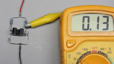
Use a digital multimeter to check the proper functionality of the sensor unit. Connect the photoelectric sensor to a DC voltage (usually 3.3 or 5V). Dial voltage measurement and connect the multimeter to ground and the output of the sensor unit ("+" pin at the photo transistor). The voltage read should be below 0.5V. If the light of the LED is blocked (e.g. with the blade of a knife), the reading should be near that of the input voltage. Sensor disc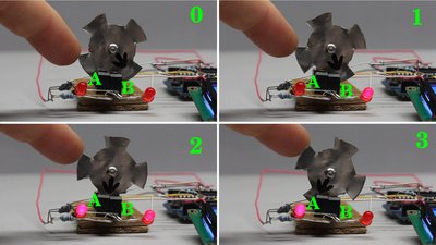
In order to detect rotational movement, two light sensors are needed. Teeth and gaps of the sensor disc must be wide enough to block or let pass the infrared light of both LEDs simultaneously. Whenever the disc rotates, the signal level at one of the sensor units changes at a time. If the cycle from 0 - 3 is passed once, the sensor disc has been rotating for one teeth (or gap, depending on the starting point). For a full turn of the sensor disc, that cycle is passed four times; the state at the two outputs changed 16 times by what a full turn is divided into 16 steps, each with an angular movement of 22.5 degrees. The more teeth, the higher the resolution of the rotational encoder. 6 Teeth result in 24 steps for a full turn and so we get approximately 15 degrees per step. Output signals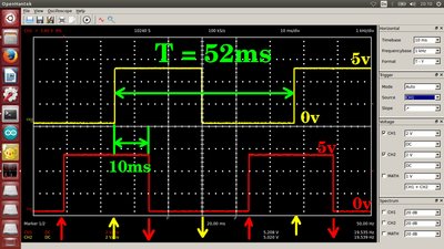
Oscilloscope plot of a mechanical encoder while spinning with constant speed. The resulting curve is a square wave signal. The lower curve is shifted to the right by 10ms. Ideally that phase shift should equal a quarter of the periodical time, which is Motor control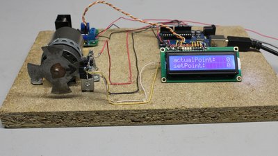
Through an H bridge a microcontroller can switch an electric motor in either direction. By software, the motor can be turned on until the sensor disc has been rotating for one step. In doing so a conventional brushed DC motor can be converted into a stepper motor. Number and direction of steps is commanded through the USB interface from a computer. If 16 steps are transmitted with a single command, the motor does a full turn without a break (assuming a sensor disc having four teeth). The set point is permanently compared to the actual position of the sensor disc by the microcontroller and whenever there is a variation, the motor is controlled in such a way that the error gets minimized. The Arduino can process up to 1600 pulses per second. At a revolution speed of 6000rpm (=100 revolutions per second), a sensor disc with four teeth can be scanned by the control loop. Examples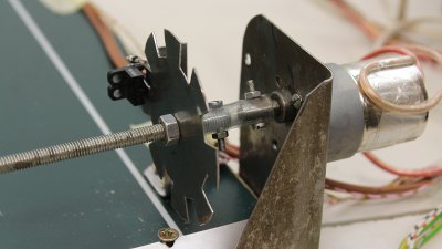
The linear movement of my CNC machines v0.6 and v2.0 is done by DC motors with encoder discs. Through a threaded rod the rotational movement of the geared DC motors is turned into linear movement. 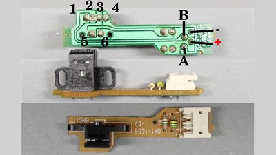
That sensor is from an old printer. If you can't find a datasheet, you can guess what pin belongs to what functionality. The side with the phototransistor has four pins (1-4), that of the LED only two (5+6). Ground of the LED side and the sensor side are very likely joined. That's true for pin 3 and 6 at this board. Thus, minus of the voltage source has to be connected to those pins. The output pins of the sensor are joined directly with the pins of the plug (A+B). That's true for pin 1 and 4 at the sensor side. The last pin of the plug must be that of the positive supply voltage. Plus runs to pin 5 through a series resistor (R1) and directly to pin 2. There is a capacitor between plus and minus (C1). Test the board with 3.3V first (connected to the plug pins, not directly to the sensor pins!). The voltage at pins A and B should be close to 0V. If the light of the LED is blocked by the blade of a knife, the recorded voltage must be close to the input voltage (3.3V). If the voltage at the sensor pins doesn't drop below 0.5V when the blade is removed, you can try to operate the sensor using 5V input voltage. 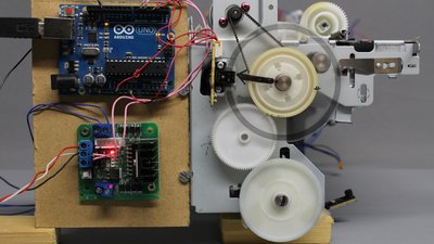
The sensor disc of the printer has approximately 3000 very thin lines. At one revolution per second we get 12000 transitions at the inputs of the microcontroller each second. I have written a new, more efficient sketch using interrupts to be able to control that motor. Nonetheless the revolution speed of the printer motor had to be reduced by pulse-width modulation to avoid skipping pulses. 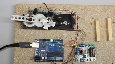
Digital servo made of the drive used to open and close the tray of an old optical drive. As mentioned before, the angular resolution can be increased by using a sensor disc with more teeth. You can also attach the sensor disc to a gear wheel of the transmission instead of using the output shaft. The gear with the sensor unit turns with an average angle of 22.5 degrees per step when using a disc with 4 teeth. With the transmission of 13:1 from the sensor wheel to the output shaft we get just 1.7 degrees per step. Note that there is always clearance caused by a transmission which lowers that academical value. 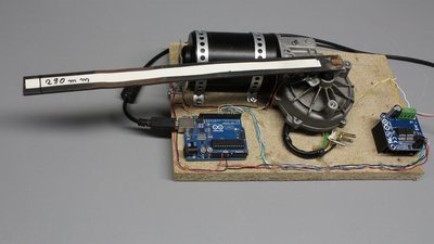
If you need a really powerful servo, you can use a wiper motor. The H bridge has a BTS7960 chipset which is good for a continuous current of up to 43A (with a heat sink). Arrangement of the sensors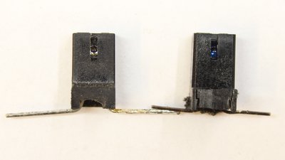
The light emitting and sensing areas of transmissive photo sensors are usually limited to a slit with a width of just 1mm at the center of the device. 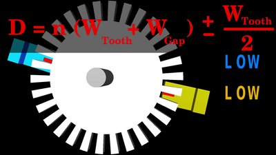
To get a more compact arrangement of a rotary encoder, the tooth width can be reduced to twice the width of the slit at the center of the photo sensor. The 2nd sensor can be put anywhere on the wheel as long as it is an integer of the tooth and gap width plus or minus half a tooth width apart from the first one. With a 1mm slit, the resulting tooth width is 2mm. For a sensor disc with 30 teeth we get a radius of One tooth as well as one gap is DownloadsSome of the example circuits in the video are available as download package. Leave a comment or send me a mail if you are missing something in this package.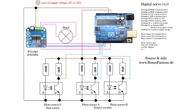
Circuit of the digital wiper motor servo. <<< Servos Encoder disc (2) >>> News The Project Technology RoboSpatium Contribute Subject index Archives Download Responses Games Links Gadgets Contact Imprint |
|
|