|
|
|
|
News The Project Technology RoboSpatium Contribute Subject index Download Responses Games Gadgets Contact <<< Stationary engines CNC v0.6 >>> CNC v0.5The video about CNC v0.5A good point to start CNC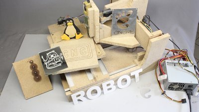
The CNC shown here is meant to be an educational machine rather than a productional tool. The machine has a work area of 20 times 20 cm and a base area of approximately 50 times 60 centimeters. It is controlled through an Arduino Uno and the axes are driven by 3 servos. The machine is composed of materials available in a do it yourself store. 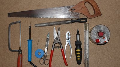
You can build this machine on a weekend using only a few tools. All you need is a metal and a wood saw, a soldering iron, a file, a caliper, metal shears or old normal sissors, a screwdriver, a folding rule (or at least a part of it) and some epoxy. Additionally I used some hot glue and I have made two wrenches from a piece of iron. The frame is made of 20mm chipboard. Parts list
Mechanics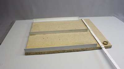
The base plate is made of 20mm chipboard with the dimensions 40x50cm. The axes are guided by 1mm aluminum bars of the dimensions 25 times 25 mm. Three of those aluminum angles with a length of 40cm are glued on the base plate. 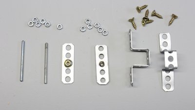
The movement is done through 3mm threaded bars. Two brass nuts have to be soldered on two pieces of perforated metal stripes. Using brass nuts in combination with iron bars reduces abrasion. The wear on the iron threads is lower than that on the brass nuts, thus the treaded bars won't get destroyed over time. On the other hand the cheap brass nuts might have to be replaced after several hours of operation. 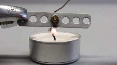
If your soldering iron hasn't enough power to heat up the metal stripe, you can use a candle. 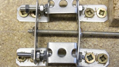
The second metal stripe is mounted in such a way that the clearance is as low as possible. The lower the clearance, the higher the friction. The right adjustment is a compromise between friction and clearance. 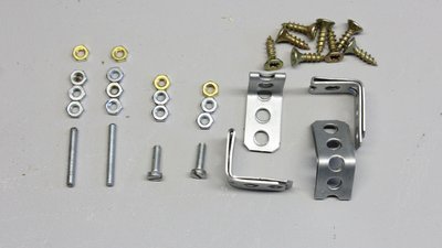
The axes are guided by the middle aluminum bar using perforated metal stripes as well as 3 millimeters screws and nuts. 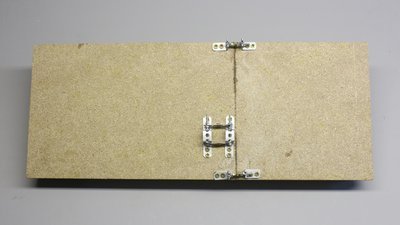
Once again I am using brass nuts at the ends of the screws to reduce abrasion of the aluminum angles. Same as with the threaded bars, the adjustment is a compromise between low clearance and friction. 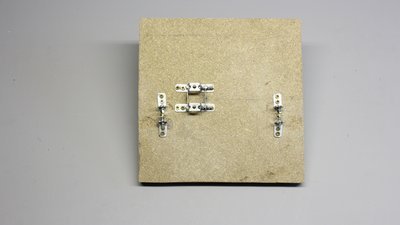
The mechanism for the Y axis is build in the same way. 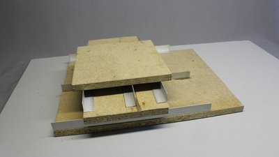
Both axes can process linear movement. 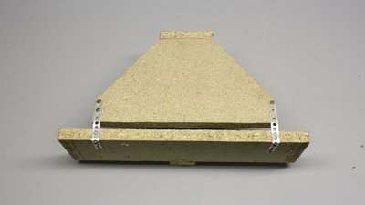
The vertical axes uses two hinges made of perforated metal stripes. 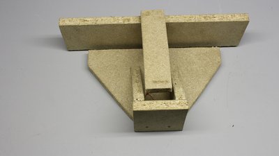
Here you can see the original version. The construction has ben modified slightly during testing. 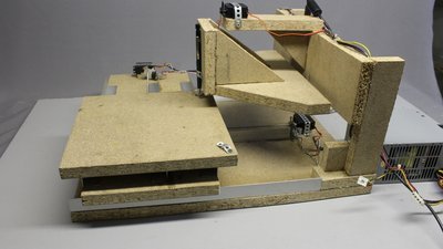
This version of the mechanics has been modified... 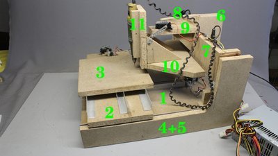
...to be able to cut 2mm plastics. The more solid, the better! Numbering of all parts according to the constructional drawing. 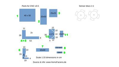
You can get the constructional drawing including the control software and the schematics at the download section. Servos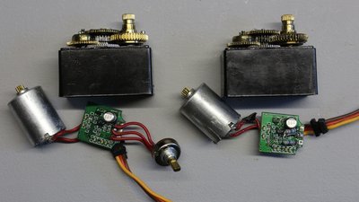
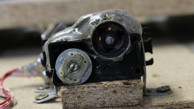
The axes are driven by standard servos having metal gears and ball bearings. Two of the servos have to be modified for continuous rotation. First, the stopper on the gear at the output shaft has to be grinded. After that, the potentiometer has to be removed and replaced by a voltage divider composed of two constant resistors (I have used 16kΩ). 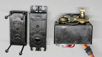
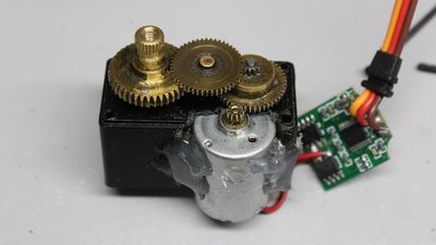
The gear ratio of the servos has to be lowered. When removing just one of the gear wheels, the motor has to be mounted on a new position. The case of the servo has to be cut to bring the motor close enough to the first gear wheel. I have used hot glue but you can also use some epoxy. 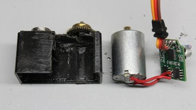
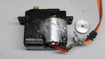
The servos I am using are not very reliable - one broke while recording the video. The weak point are the brushes inside the motor. At the broken motor, the brushes deformed in such a way that the terminals were shortened by what the servo board smoked up. 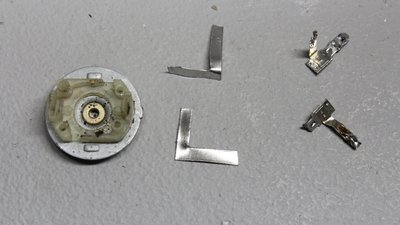
I have opened the motor and cut new, more solid brushes from a tin can. The new board is from another standard servo I had in stock. 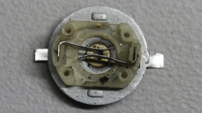
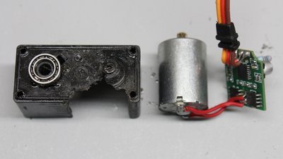
After opening the second servo I saw that the brushes of that motor were also in a very bad condition. I used some solder to stabilize the ends of the brushes by what this servo still runs fine. 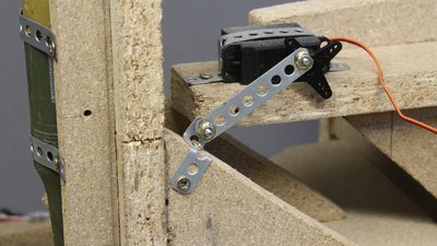
The third axis is moved by a standard servo without modifications. Electronics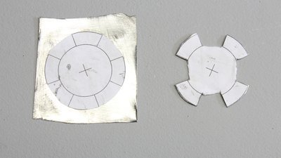
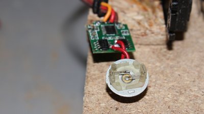
The sensor disc for the rotary encoder is cut from a tin can. That's what old scissors or metal shears are good for - the center hole is made without a drill using a 3mm nail and a hammer (or a stone). 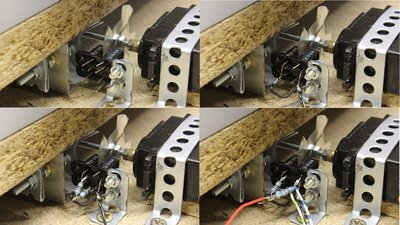
The rotational encoder is scanned by two photo sensors. The state of the sensors is read by the Arduino Uno. We get 16 steps per revolution. A full turn of the threaded bar causes a linear movement of 0.5mm. Therewith we get a linear movement of 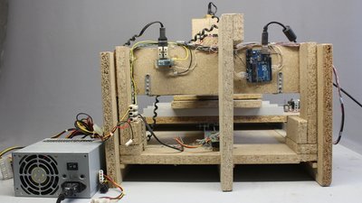
The Arduino is mounted at the back side of the CNC machine. There is a 12V relay used to switch the router. The relay is controlled by the Arduino through a small signal transistor. An old computer power supply feeds the machine with electricity. 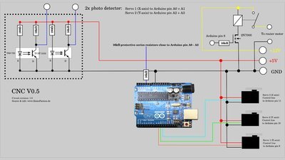
You can get the schematics with the software at the column download. Accuracy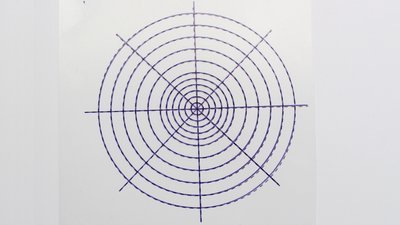
I have plotted a test pattern with a ball pen. The plot is compared with that pattern printed on a foil using an ink jet printer. There are noticeable deviations, but considering the simple construction, the result is not too bad. 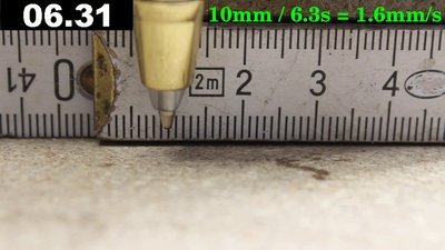
The maximum speed is just around one millimeter per second - you need patience when working with that machine... 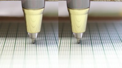
When moving the pen to one point from both directions, you can determine how precisely you have adjusted the drive. The error is just a minor fraction of a millimeter - not so bad for that cheap machine. 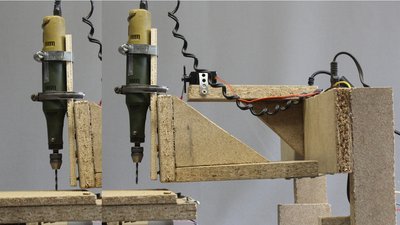
When lowering the vertical axis, there is inevitably also a movement along the X axis and the router tilts slightly. Both causes an oval shaped drill hole in theory. 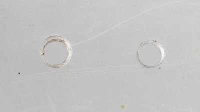
In practice that movement is negligible. To the left, you can see the hole drilled with the CNC machine, the hole to the right was done with a drill press using the same 3mm drill bit. The CNC machine is not free from clearance, thus the hole is not as smooth as it ideally should be, but it's not oval. Examples of use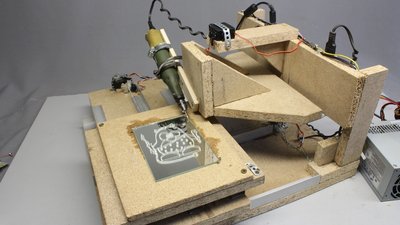
Engraving glass works fine - the router has to be mounted with an angle to the horizontal plane. 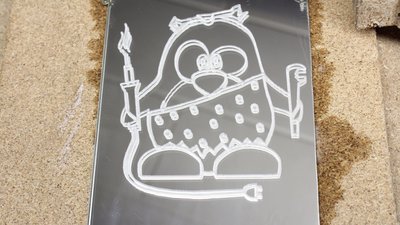
The diamond milling cutter has to be cooled with some water during engraving work. For the graphics shown here, the machine needed more than an hour. 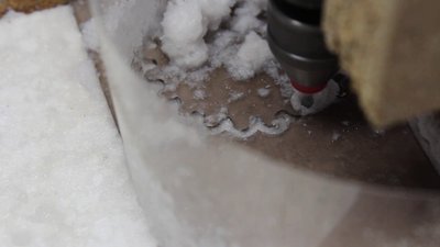
The software computes special gears with round teeth. I have used 2mm acrylic plastic to cut some gear wheels. The machine is to weak for more solid materials. Cool the drill bit when cutting plastics to avoid that material from melting. When moving along a path, the side load acting on the router bit twists the mechanics of this simple CNC. To get at least usable results, the cutting has to be done in two or more runs. The router is lowered to just half the thickness of the plastic in the first run. The router cuts through the plate in the last run. Use a file to finish the gear wheel. 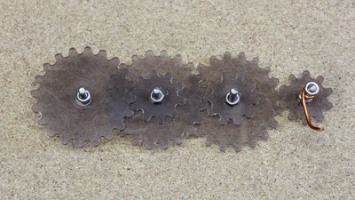
After some tries, the quality of the parts was sufficient to build a gear train. 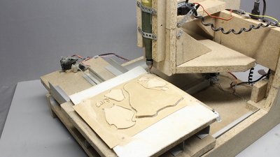
The router can cut 1mm plywood more easily, thus you can higher the speed of the machine slightly. The parts of the puzzle are mirror inverted because the edges at the bottom of the plywood are cut smoother than those at the top of the plate. Approximately one hour is needed to cut all parts of the puzzle - this not a speed record breaking CNC machine. When the machine has finished it's work, the edges have to be smoothened with sandpaper - put raw material in and get perfect parts out is nothing you get with cheap machines. 
With some paint and glue we get a well known bird: It's hardly recommended to rethink your software strategy if you don't know the name of that penguin. With a jigsaw you can cut the parts of this puzzle faster with a similar precision, but that's what anybody could do... 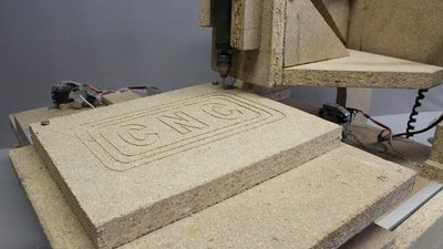
You can also engrave wood: Here I am engraving 20mm chipboard as used for the frame of the machine. The mechanism of the CNC isn't ideally plain and the drive doesn't move idealy in parallel to the base plate. As a result, the router is diving into the material with varying depth when moving along a path. You must have a close look at the plate to notice that error. 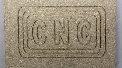
You can lower the router for a second run. Leave all other parameters of the software unchanged. The paths are clearly visible now. The cutting edge isn't perfectly smooth, thus you can't engrave tiny structures with this machine - the characters shown here are approximately 5cm high. 
For this machine, aluminum is "heavy metal"! The mechanism is bent clearly by what the router vibrates sometimes hardly while cutting the material. Mainly the movement along the vertical axis causes improper cutting lines. The result is eventually acceptable, but definitely not very good. You have to build a more solid mechanics if you intend to cut aluminum. You won't be able to process solid aluminum blocks! 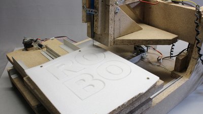
The 3mm plate of Depron processed here can be cut very easily. The material isn't cut with a router but by using a soldering iron with a 1mm copper wire at it's tip. Consequently, processing Depron with that CNC machine is more quietly. The length of the copper wire should be chosen in such a way that the temperature is just enough to melt the Depron - that reduces the bad smell of evaporating plastics. The width of the cutting line is approximately 2mm and there is almost not side load on the tip of the soldering iron. 
Depron is cheaply available and it is a proper material to demonstrate how a CNC machine works. Software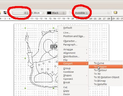
The software used to control the machine is written in C and it is running from the command line. With the menu you can choose the test pattern and set some variables. The supported vector format is "Scalable Vector Graphics (*.svg)" with some special things to note: No areas are drawn, only their outlines. All paths (also the outlines of an area) must be set to "Polygon". I have tested the functionality with graphics edited and exported as svg by Libre Office Draw. You can get the source code with some example vector files at the Download section. <<< Stationary engines CNC v0.6 >>> News The Project Technology RoboSpatium Contribute Subject index Archives Download Responses Games Links Gadgets Contact Imprint |
|||||||||||||||||||||||||||||||||
|
|